
Pneumatic cone clutch fan drive having threaded attachment method for drive shaft of clutch to hub mounting

a technology of clutch fan and clutch shaft, which is applied in the direction of interlocking clutches, couplings, machines/engines, etc., can solve the problem of limiting the complexity of design and manufacture of the fan driv

Active Publication Date: 2006-09-05
BORGWARNER INC
View PDF16 Cites 7 Cited by
  • Summary
  • Abstract
  • Description
  • Claims
  • Application Information

AI Technical Summary

Benefits of technology

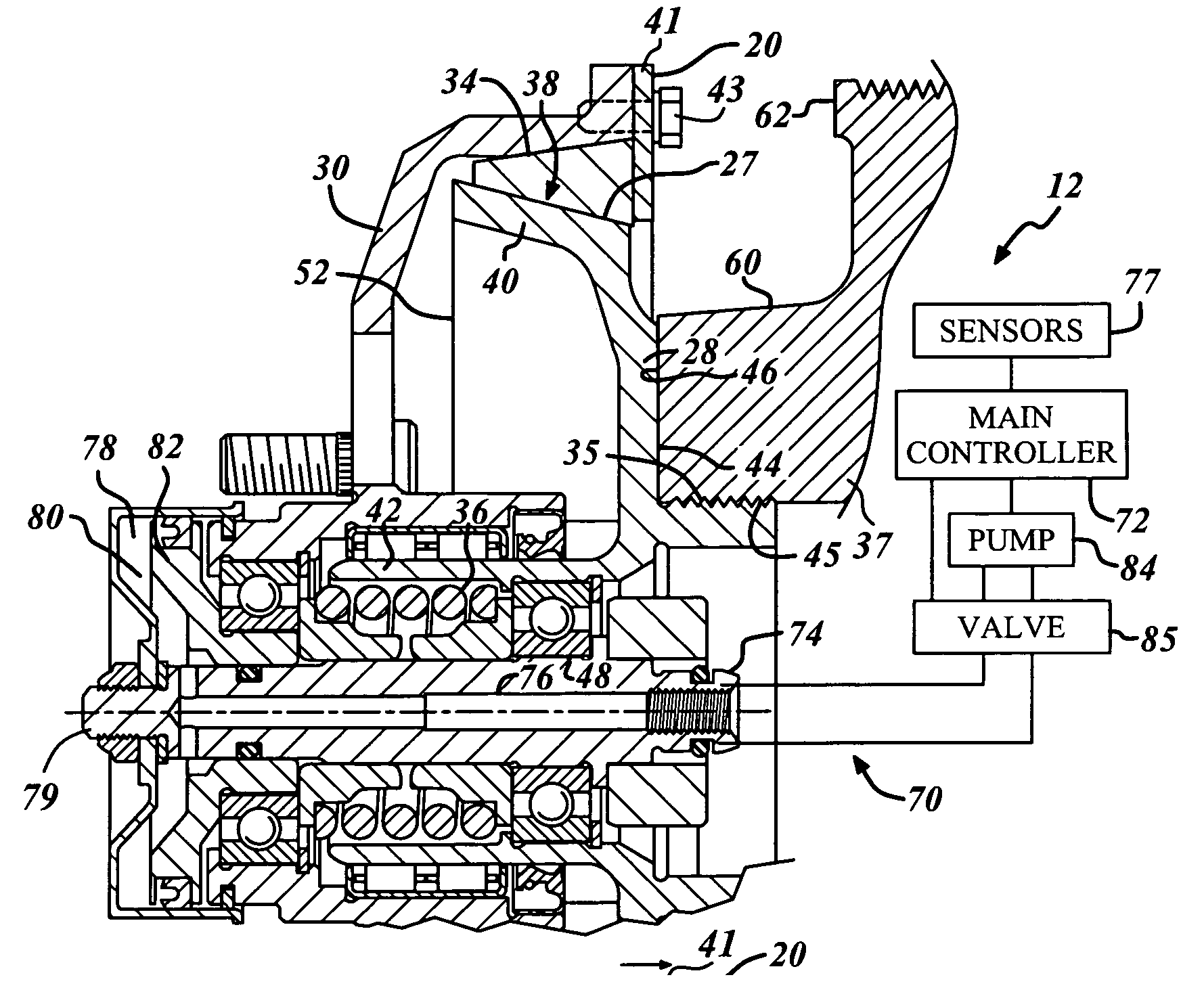
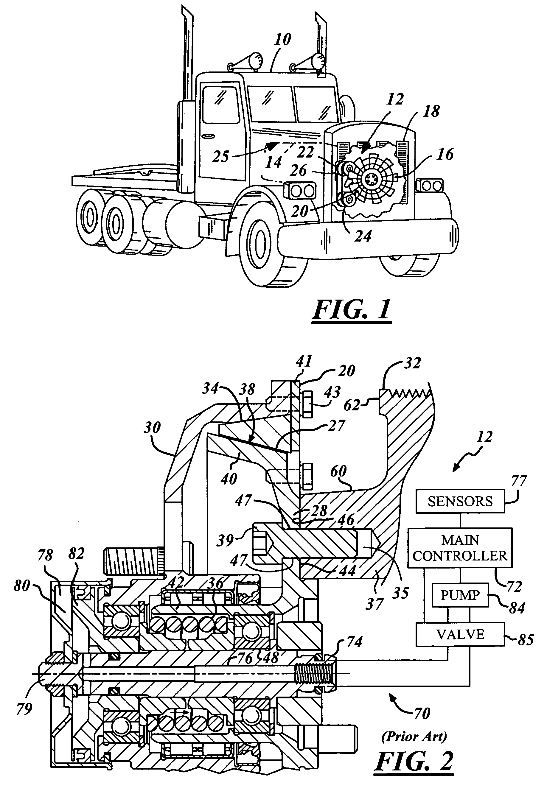
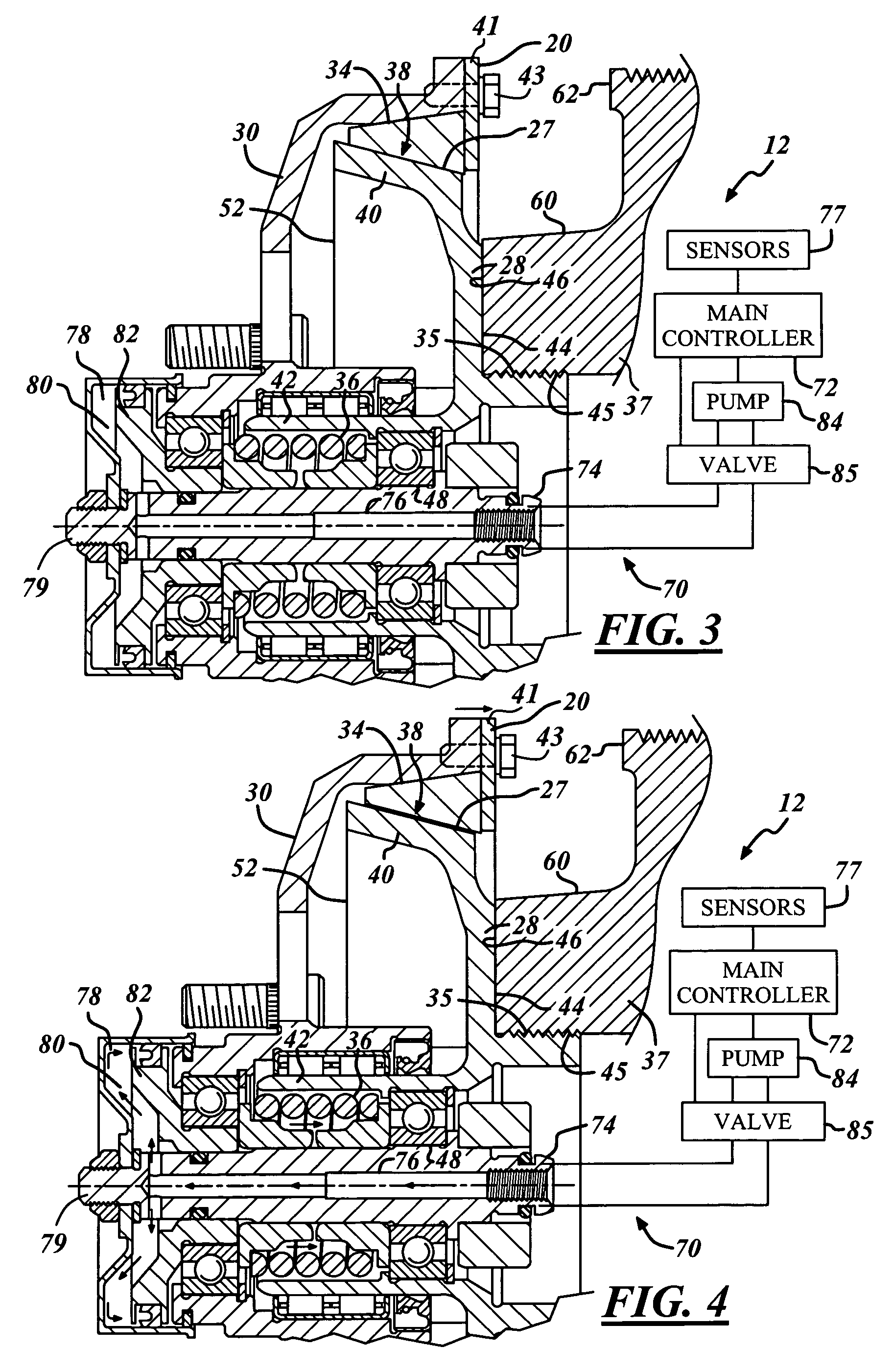
[0009]In accordance with the objects of the present invention, the rotating shaft is formed with an integral external threaded portion that is designed to mate with a corresponding internal threaded portion of the hub. The threaded portions replace the holes and corresponding cap screws that are traditionally used to attach the drive shaft to the hub of the drive pulley. The new design limits the complexity of design and manufacture of the fan drive.

Problems solved by technology

The new design limits the complexity of design and manufacture of the fan drive.

Method used


Image

  • Pneumatic cone clutch fan drive having threaded attachment method for drive shaft of clutch to hub mounting
  • Pneumatic cone clutch fan drive having threaded attachment method for drive shaft of clutch to hub mounting
  • Pneumatic cone clutch fan drive having threaded attachment method for drive shaft of clutch to hub mounting

Examples


Embodiment Construction

[0015]In the following figures the same reference numerals will be used to refer to the same components. While the present invention is described primarily with respect to a cone clutch fan drive system, the present invention may be adapted and applied to various systems including: hydraulic systems, electrical systems, pneudraulic systems, mechanical systems, pneumatic systems, vehicle systems, cooling systems, fan drive systems, friction drive systems, or other systems.

[0016]In the following description, various operating parameters and components are described for one constructed embodiment. These specific parameters and components are included as examples and are not meant to be limiting.

[0017]Also, in the following description various fan drive components and assemblies are described as an illustrative example. The fan drive components and assemblies may be modified depending upon the application.

[0018]Referring now to FIG. 1, a perspective view of a vehicle 10 utilizing a flui...


PUM


Abstract

An on / off clutch assembly is disclosed having a simplified method for attaching the drive shaft to the hub portion of the drive pulley. The rotating shaft is formed with an integral external threaded portion that is designed to mate with a corresponding internal threaded portion of the hub. The external threaded portion, in conjunction with the internal threaded portion, replace the holes and corresponding cap screws that are used to attach the drive shaft to the hub in current designs. The new design limits the complexity of design and manufacture of the fan drive.

Description

TECHNICAL FIELD[0001]The present invention relates generally to a cone clutch fan drives and more particularly to a pneumatic cone clutch fan drive having a threaded attachment method for coupling the drive shaft of the clutch to the hub mounting.BACKGROUND OF THE INVENTION[0002]Vehicle engines commonly utilize cooling assemblies to remove excess heat from the engine and maintain an optimal operating temperature. The cooling assembly pumps a coolant through the engine and other components in order to control engine temperature. Heat generated within the engine and other components is absorbed by the coolant and dispersed into the surrounding atmosphere through the use of a radiator. In order to improve dispersal by the radiator, it is common to utilize fan assemblies to draw or force air past the radiator to assist in temperature transmission.[0003]It is not always desirable for such fan assemblies to be run continuously. At times, it is desirable for the temperature within the cool...

Claims


Application Information

Patent Timeline
Patent Type & Authority Patents(United States)
IPC IPC(8): F01P7/02
CPCF01P7/085F16D25/12F16D25/0632F16D1/06
Inventor WAYMAN, NATHANIEL ERIC
Owner BORGWARNER INC
Learn More