Multi-spark type ignition system

a multi-spark type, ignition system technology, applied in the direction of engine ignition, machines/engines, other installations, etc., can solve the problem of power transistors being heated more, and achieve the effect of preventing excessive rising

Active Publication Date: 2006-09-05
DENSO CORP
View PDF10 Cites 15 Cited by
  • Summary
  • Abstract
  • Description
  • Claims
  • Application Information

AI Technical Summary

Benefits of technology

[0008]Another object of the invention is to provide a multi-spark ignition system in which the temperature of the power transistor is also prevented from excessively rising even if the power transistor is locked into a turning-on state by accident.
[0009]According to a preferred embodiment of the invention, a multi-spark type ignition system for an internal combustion engine includes an electric power source, a energy storage coil connected to the electric power source for storing electric energy supplied by the electric power source, an energy storage capacitor for storing electric energy discharged from the energy storage coil, a first switching element for switching on or off supply of the electric energy from the electric power source and supply from the energy storage coil to the energy storage capacitor, an ignition coil connected to the energy storage capacitor, a second switching element for switching on or off supply of the electric energy from the energy storage capacitor, and an external resistor connected between the energy storage coil and the first transistor so as to bypass the energy storage capacitor, thereby limiting current flowing through the first transistor. Therefore, the energy to be stored by the energy storage coil can be kept without increasing the number of turns thereof or the size thereof, while current flowing through the first switching element can be appropriately limited by the external resistor.

Problems solved by technology

However, if the power transistor is kept turn on due to some failure, the power transistor may be heated more as the resistance of the energy storage coil becomes smaller because the current flowing through the power transistor can not be suitably limited.

Method used


Image

  • Multi-spark type ignition system
  • Multi-spark type ignition system
  • Multi-spark type ignition system

Examples


Embodiment Construction

[0015]A preferred embodiment of the invention will be described with reference to the appended drawings.

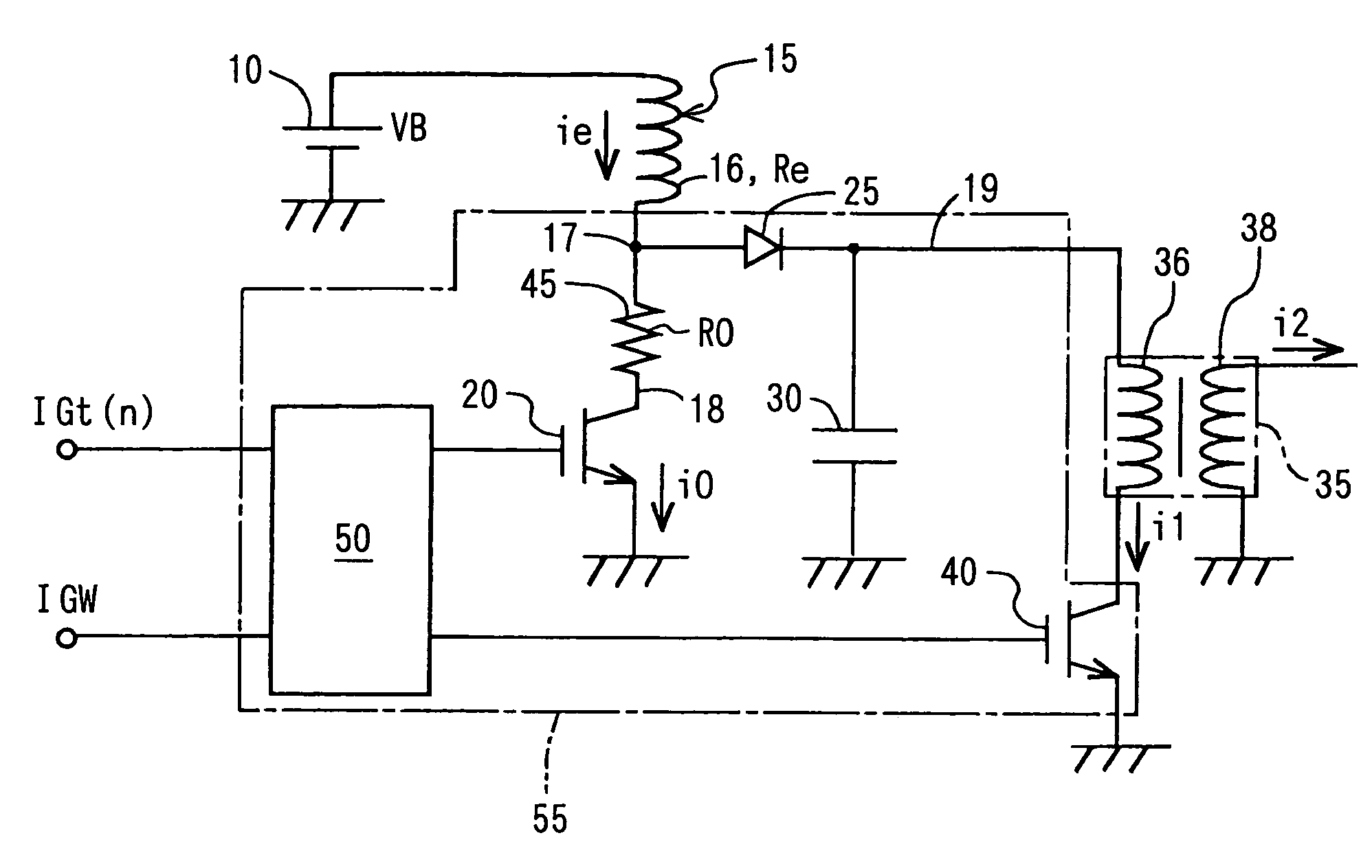
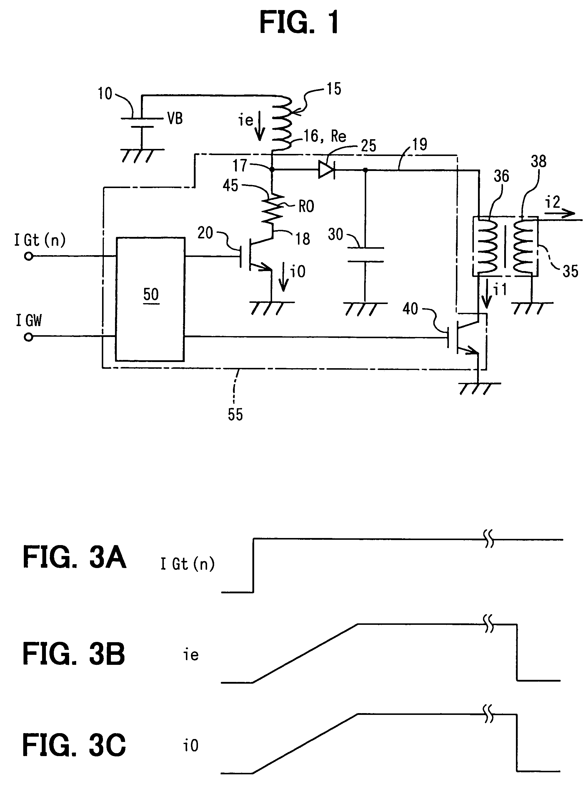
[0016]As shown in FIG. 1, a vehicle battery 10, a multi-spark type ignition system includes a energy storage coil 15, a first power transistor (hereinafter referred to as the first transistor) 20, an energy storage capacitor 30, an ignition coil 35, a second power transistor (hereinafter referred to as the second transistor) 40, an external resistor 45 and a multi-spark control circuit 50. Incidentally, there are as many ignition coils 35 and the second transistors 40 as cylinders of an engine to which this system is applied. Each ignition coil 35 has a primary coil 36 and a secondary coil 38.

[0017]The energy storage coil 15 has an input terminal connected to a high-side terminal of the vehicle battery 10 and an output terminal 17 connected to one end of the external resistor 45. The other end of the external resistor 45 is connected to the collector 18 of the first transistor 20....


PUM


Abstract

A multi-spark type ignition system for an internal combustion engine has a compact energy storage coil. The multi-spark type ignition system includes a energy storage coil, an energy storage capacitor, a first power transistor that switches on or off supply of electric energy from a battery and the electric energy from the energy storage coil to the energy storage capacitor, a second power transistor connected to the energy storage capacitor and to an ignition coil and an external resistor, connected between the energy storage coil and the first power transistor so as to bypass the energy storage capacitor. The second power transistor switches on or off the primary current. The external resistor limits current flowing through the first power transistor, thereby limiting temperature rise of the first power transistor.

Description

CROSS REFERENCE TO RELATED APPLICATION[0001]The present application is based on and claims priority from Japanese Patent Applications: 2004-159012, filed May 28, 2004; and 2005-4123, filed Jan. 11, 2005; the contents of which are incorporated herein by reference.BACKGROUND OF THE INVENTION[0002]1. Field of the Invention[0003]The present invention relates to an ignition system for a vehicle internal combustion engine, and, particularly, a multi-spark type ignition system that repeatedly ignites fuel each time it is supplied to each cylinder of an internal combustion engine.[0004]2. Description of the Related Art[0005]U.S. Pat. Nos. 4,892,080 and 5,056,496 disclose multi-spark type ignition systems in which as many ignition coils as cylinders of an internal combustion engine are employed. Such a system also includes an energy storage coil, a energy storage capacitor and switching power transistors for intermittently controlling supply of electric energy. One of the switching transisto...

Claims


Application Information

Patent Timeline
Patent Type & Authority Patents(United States)
IPC IPC(8): F02P15/10F02P3/06
CPCF02P15/10F02P3/06F02P3/0876
Inventor TORIYAMA, MAKOTO
Owner DENSO CORP
Why Eureka
Try Eureka