Make-up control system for tubulars

a technology of make-up control and tubulars, which is applied in the direction of drilling pipes, surveying, and well accessories, etc., can solve the problems of not being able to meet the needs hydraulic power tongs have several limitations, and hydraulic power tongs should be torque-limited, so as to achieve the effect of all of these features, the design may be impractical to implement in the harsh conditions of oil well drilling rigs

Active Publication Date: 2006-09-05
VARCO I P INC
View PDF27 Cites 68 Cited by
  • Summary
  • Abstract
  • Description
  • Claims
  • Application Information

AI Technical Summary

Benefits of technology

[0005]The present invention is directed to a make-up control system for creating a threaded connection between a first tubular and a second tubular using a top drive motor. The control system of the current invention monitors, at least one of the number of turns, the torque, and the rotational speed that are applied to the first tubular by a top drive during a make-up process and halts the make-up process if a torque limit is reached. The top drive is an oil and gas well structure that is typically connected to one or more tubulars to provide torque and rotational speed control to the tubulars during the drilling of a wellbore. Top drives are typically not used during make-up processes because of the precise control needed to prevent damage to the treads of the tubulars being connected. As such, the control system of the present invention closely monitors and controls the torque and rotational speed that the top drive applies to the tubulars to protect the threads of the tubulars from damage during the make-up process.

Problems solved by technology

Hydraulic power tongs have several limitations.
However, in other portions of the make-up process, the hydraulic power tongs should be torque-limited in order to protect the tubulars from damage if they are inadvertently cross-threaded.
While it may be possible to design practical hydraulic power tongs with some of these features, a design with all of these features may be impractical to implement in the harsh conditions of an oil well drilling rig.
In addition, the repetitive processing of the tubulars may lead to fatigue and boredom in the skilled operators, thus resulting in inattention to the make-up process.

Method used


Image

  • Make-up control system for tubulars
  • Make-up control system for tubulars
  • Make-up control system for tubulars

Examples


Embodiment Construction

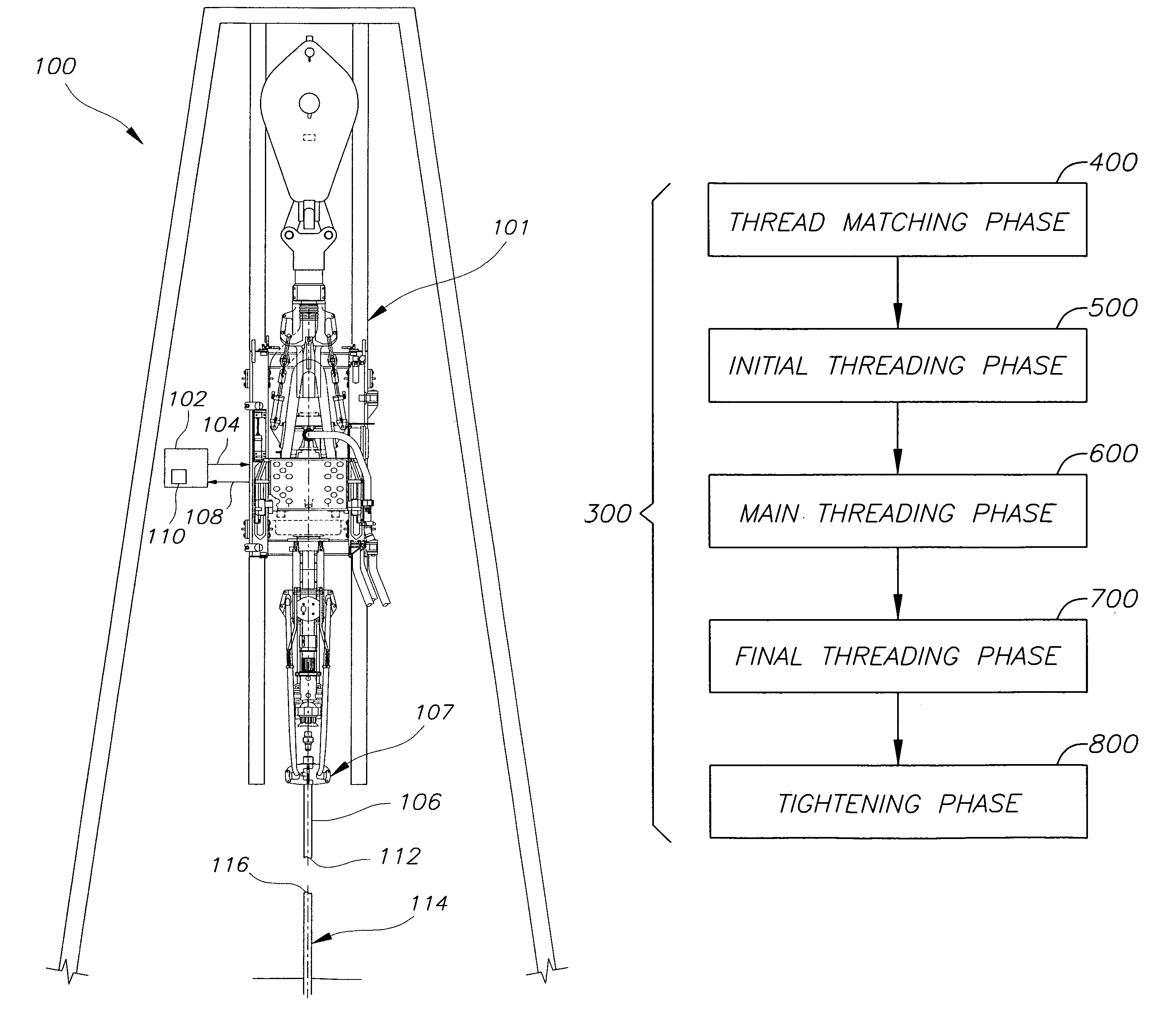
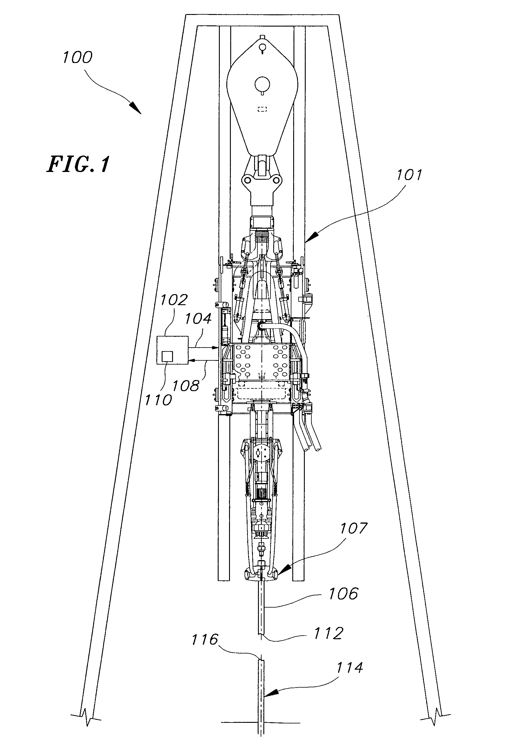
[0019]A shown in FIGS. 1–10, embodiments of the present invention are directed to a make-up control system that may be used to create threaded connections between tubulars during a multi-phased make-up process.

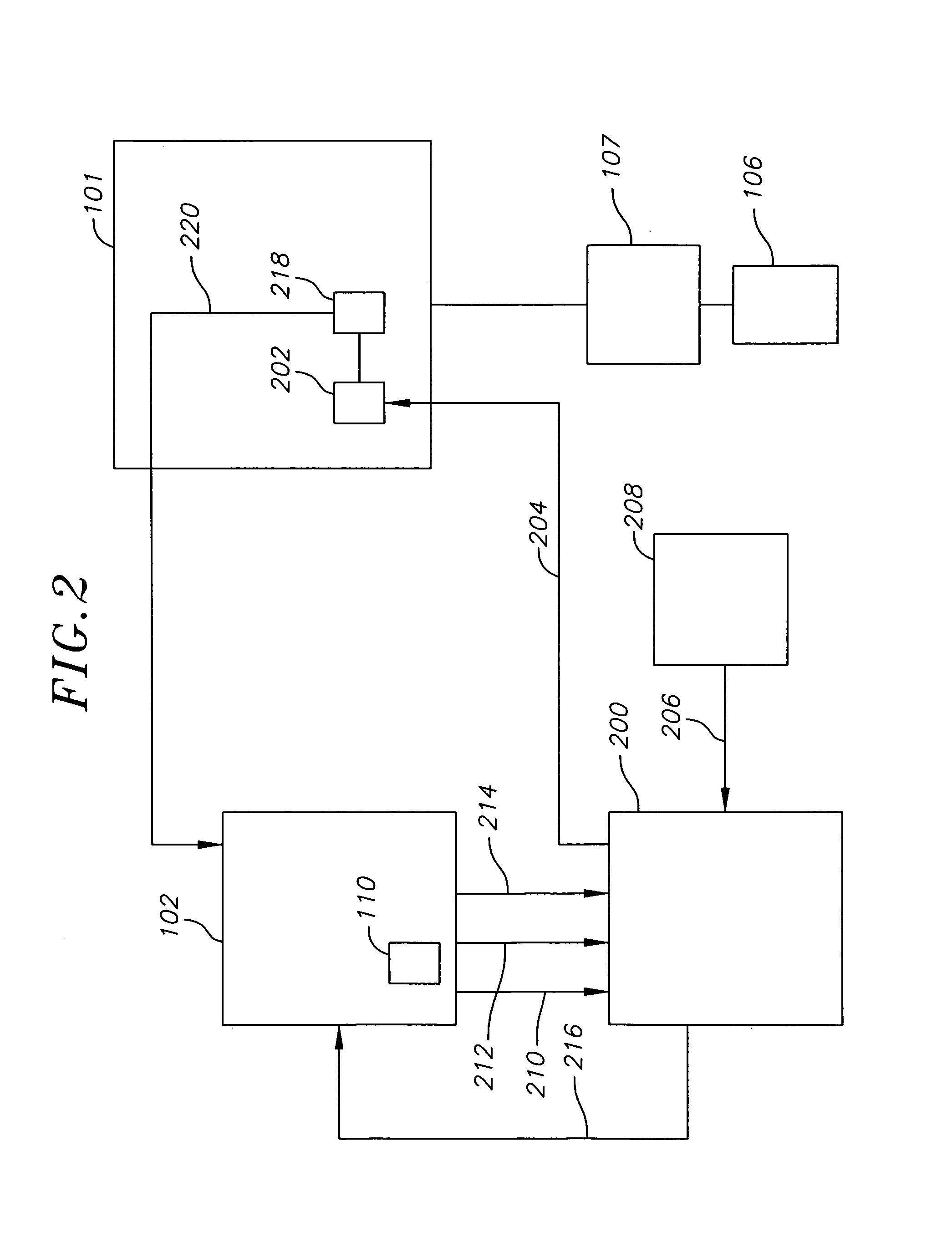
[0020]In one embodiment, the make-up control system includes a top drive that is operably connected to a controller for providing number of turns, torque and rotational speed control during the make-up process. In such an embodiment, a rotatable tubular is rotated by the top drive under the control of the controller to create a threaded connection with a stationary tubular.

[0021]There are several standard phases to a making-up process. For example, first the make-up control system matches the threads of the tubulars by rotating the rotatable tubular in a direction opposite the threading direction of the threads of the rotatable tubular during a thread matching phase. Once the threads of the tubulars have been matched, the make-up control system rotates the rotatable tubular in...


PUM


Abstract

A make-up control method and system for creating a threaded connection between a first tubular and a second tubular are provided. The make-up control system including a top drive connected to the first tubular and a controller operably connected to the top drive that sends at least one command signal to the top drive. The top drive generating a torque and a rotational speed in response to the at least one command signal that are applied to the first tubular during a make-up process between the first and second tubulars. The top drive also generating a torque feedback signal that is transmitted to the controller. The controller using the feedback signals to monitor the torque and rotational speed that are applied to the first tubular during the make-up process. The controller halting the make-up process when a predetermined torque limit is reached.

Description

FIELD OF THE INVENTION[0001]The present invention relates generally to the field of oil and gas well drilling systems, and more specifically to a control system for making-up threaded connections between threaded tubulars, such as drill casings, using a top-drive.BACKGROUND OF THE INVENTION[0002]Oil and gas well drilling systems include numerous types of piping, referred to generally as “tubulars.” Tubulars include drill pipes, casings, and other threadably connectable oil and gas well structures. Long “strings” of joined tubulars are typically used to drill a wellbore and to prevent collapse of the wellbore after drilling. Some tubulars are fabricated with male threads on one end and female threads on the other. Other tubulars feature a male thread on either end and connections are made between tubulars using a threaded collar with two female threads. The operation of connecting a series of tubulars together to create a “string” is known as a “make-up” process.[0003]One method for ...

Claims


Application Information

Patent Timeline
Patent Type & Authority Patents(United States)
IPC IPC(8): E21B19/16E21B3/00E21B10/00E21B47/00
CPCE21B19/166
Inventor KRACIK, JOHNVAN RIJZINGEN, HANS
Owner VARCO I P INC
Why Eureka
Try Eureka