
Direct back light unit with heat exchange

a back light unit and heat exchange technology, applied in the field of back light units, can solve the problems of reducing the performance of the display panel, reducing the life of the back light unit elements, and reducing the heat produced by the display panel and the back light unit to the external environment when the display panel is operated, so as to improve the heat transfer of the back light unit, avoid serious accumulation of heat, and high thermal conductivity

Active Publication Date: 2006-09-05
AU OPTRONICS CORP
View PDF11 Cites 27 Cited by
  • Summary
  • Abstract
  • Description
  • Claims
  • Application Information

AI Technical Summary

Benefits of technology

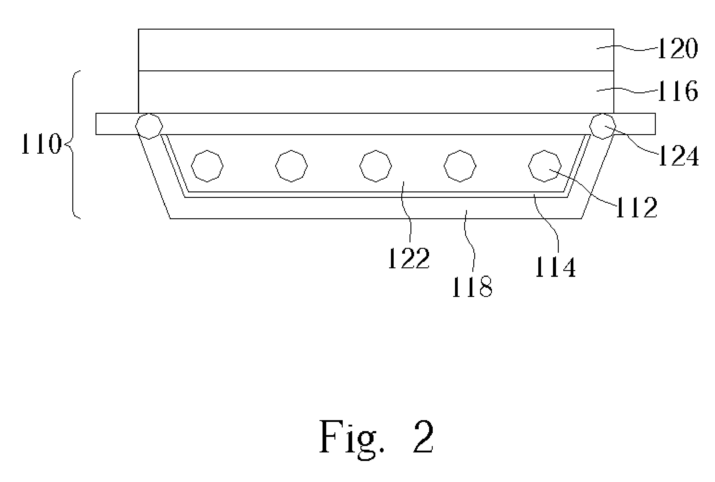
[0010]It is an advantage of the claimed invention that the back light unit comprises a plurality of heat pipes with high thermal conductivity set in the housing so that the internal portion of the back light unit can be maintained in an isothermal state. It can avoid heat being seriously accumulated around the light source generator, thus the problem of the internal devices of the back light unit being damaged by the high temperature or nun-uniform temperature distribution is solved. As a result, the claimed invention can improve the heat transfer of a back light unit, and furthermore raise the utility of light and lightness of the back light unit to make the display panel have a better performance and a longer lifetime.

Problems solved by technology

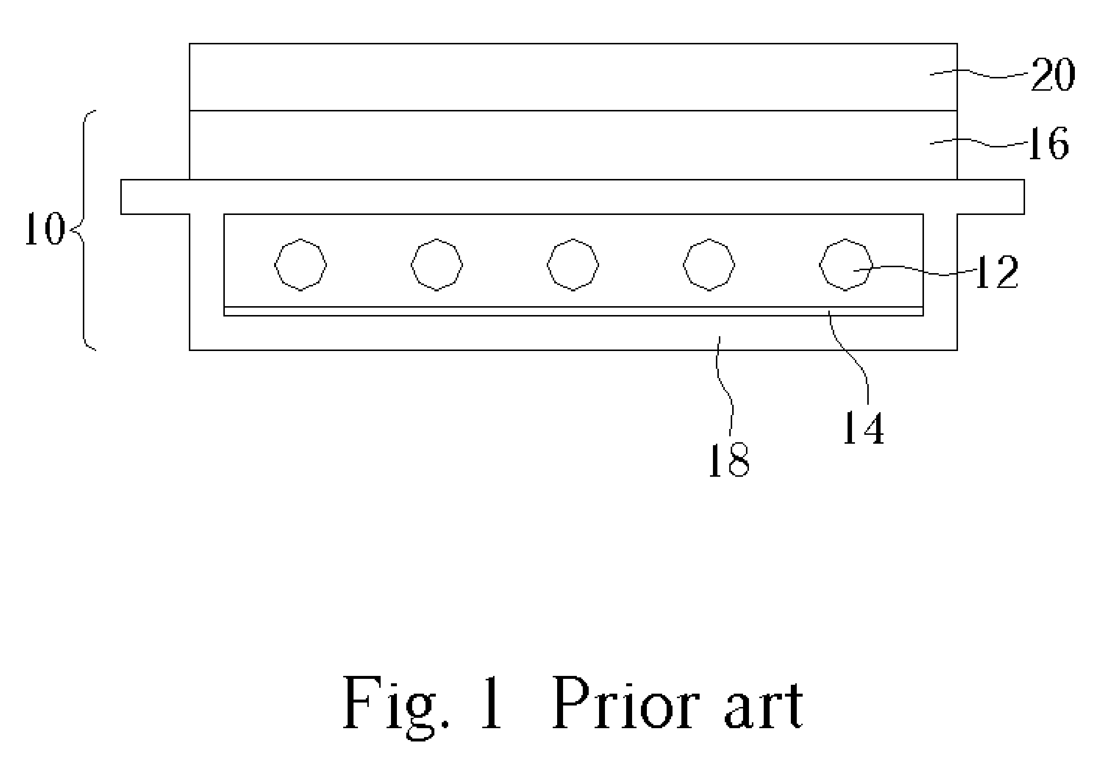
For achieving the goal of high lightness and thinness, the light source generator of a back light unit is usually set in an airtight chamber, thus it is hard to radiate the heat produced by the display panel and the back light unit to the external environment when the display panel is operated.
As the operation time becomes longer, the heat in the back light unit is accumulated and it results in the temperature around the fluorescent tubes being too high to maintain normal operation, so that the performance of the display panel will be reduced (for example, a portion of the image may flash) and the lifetime of the elements of the back light unit will be shortened.
However, as the vent holes and the fan are set, the noise of the van occurs and the dust easily intrudes into the back light unit to reduce the utility of the light.
However, there is still a limitation of increasing the radiating area according to JPN 2001-216870, thus only a small amount of heat can be dissipated, and the heat accumulation problem of the back light unit is not solved yet.
Therefore how to improve the heat dissipation of the back light unit and simultaneously raise the utility of light of the display panel, and furthermore to improve the display performance and extend the lifetime of the device is an important issue for manufactures of back light units.

Method used


Image

  • Direct back light unit with heat exchange
  • Direct back light unit with heat exchange
  • Direct back light unit with heat exchange

Examples


first embodiment

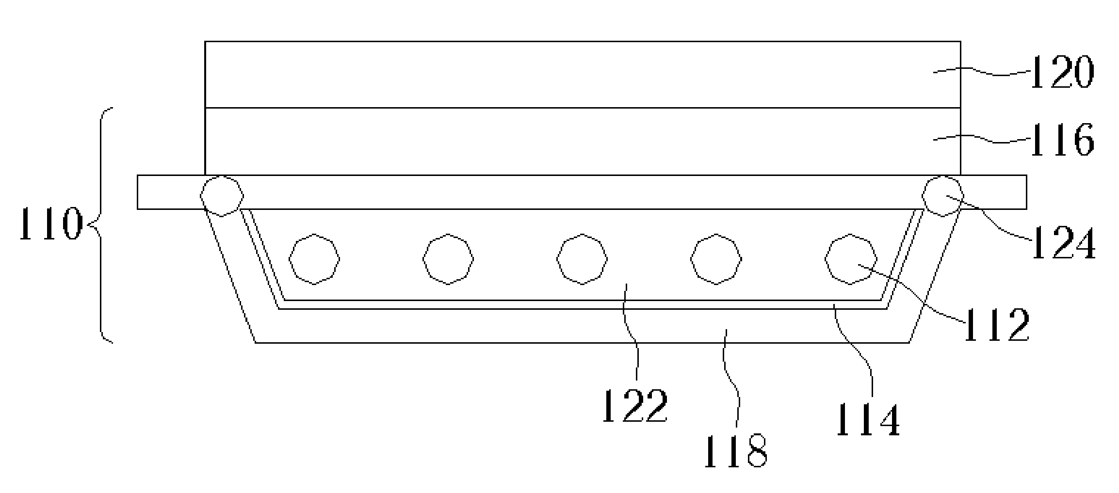
[0020]FIG. 2 is a section view of a back light unit 110 according to the present invention. FIG. 3 is a top view of the back light unit 110 in FIG. 2. The back light unit 110 is a direct-underlying type back light unit set in the backside of a display panel 120, which comprises a diffuser 116, a light source generator 112 set under the diffuser 116, and a housing 118 enclosing the light source generator 112. The back light unit 110 also comprises a diffusion film and a plurality of prisms (not shown) set on the diffuser 116 to correct the lightness and uniformity of the back light unit 110. The sidewalls of the housing 118 extend up to connect to the edge of the diffuser 116 so that a chamber 122 is formed inside the housing 118. On the inside surface of the housing 118 is a layer of reflecting film 114 so that the utility of light can be raised so that light beams emitted from the light source generator 112 will be reflected by the reflecting film 114 to pass through the chamber 12...

third embodiment

[0024]FIG. 6 is a section view of the back light unit 310 according to the present invention. FIG. 7 is a schematic diagram of the reflected light path of the bottom of the housing 318 of the back light unit in FIG. 6. The back light unit 310 is a direct-underlying type back light unit positioned in the backside of a display panel 320. The back light unit 310 comprises a diffuser 316, a light source generator 312 containing a plurality of fluorescent tubes positioned under the diffuser 316, and a housing 318 enclosing the light source generator 312, wherein the sidewalls of the housing 318 extend up to the edge of the diffuser 316 to form a chamber 322. Several heat pipes 324 composed of high conductive materials are set in the housing 318. The housing 318 also contains a plurality of reflecting sheet 328 with high radiating tendency on the bottom flat of the housing 318 and a reflecting film 314 covering the inside surface of the housing 318. For increasing the utility of light, th...


PUM

PropertyMeasurementUnit
heat-conductive aaaaaaaaaa
heat-conductiveaaaaaaaaaa
heataaaaaaaaaa

Abstract

A backlight unit with high thermal dissipation. The back light unit includes a light source generator positioned in a backside of a display panel for providing light beams to the display panel, a diffuser positioned between the light source generator and the display panel for uniformly scattering light beams from the light source generator to the display panel, and a housing enclosing the light source generator and connecting to the diffuser for reflecting the light beams to the diffuser. The housing further includes a heat pipe for being a heat transfer interface between the back light unit and an external environment.

Description

BACKGROUND OF INVENTION[0001]1. Field of the Invention[0002]The invention relates to a back light unit, and more particularly, to a back light unit with high thermal dissipation.[0003]2. Description of the Prior Art[0004]A back light unit is one of the key elements of liquid crystal display (LCD) panel and is applied to many modern electric devices, such as a digital camera, mobile phone, person digital assistant (PDA), computer monitor, and flat television. In general, the back light unit is set in the backside of a display panel. The back light unit comprises a light source generator, a diffuser positioned on the light source generator for uniformly scattering the light beams from the light source generator, and a plurality of prisms positioned on the diffuser to raise the brightness and make the lightness of the whole display panel uniform. There are two types of back light units: direct-underlying type and edge light type. In a direct-underlying type, the light source generator ...

Claims


Application Information

Patent Timeline
Patent Type & Authority Patents(United States)
IPC IPC(8): G02F1/1335G01D11/28F21V29/00F21V29/02G02F1/13357G09F13/04
CPCF21V29/004F21V29/006F21V29/89G09F13/04F21V29/74G02F1/133602F21V29/02G02F2001/133628F21V29/51F21V29/56G02F1/133628
Inventor HSIEH, CHIN-KUNYU, CHUAN-PEILIU, HAN-CHOU
Owner AU OPTRONICS CORP
Learn More