Machine tool

a technology of machine tools and tools, applied in the field of machine tools, can solve the problems of unpracticed proposals, limited machine tools, and insufficient utilization of respective working spaces, and achieve the effects of optimizing the available working space, high accuracy and fixed manner, and high rigidity

Inactive Publication Date: 2006-09-05
DECKEL MAHO PFRONTEN GMBH
View PDF18 Cites 7 Cited by
  • Summary
  • Abstract
  • Description
  • Claims
  • Application Information

AI Technical Summary

Benefits of technology

[0010]In connection with the movement of the three telescopic legs, the longitudinally slidable support of the support pipe positions the machining head or the tool inserted in the working spindle in a highly accurate and fixed manner with respect to a given working position. The slidable support of the support pipe is highly rigid and is positioned in the universal bearing, which is a...

Problems solved by technology

These machines are limited in that the utilization of the respective working spaces is not optimal.
However, on account of problems ...

Method used


Image

  • Machine tool
  • Machine tool

Examples


Embodiment Construction

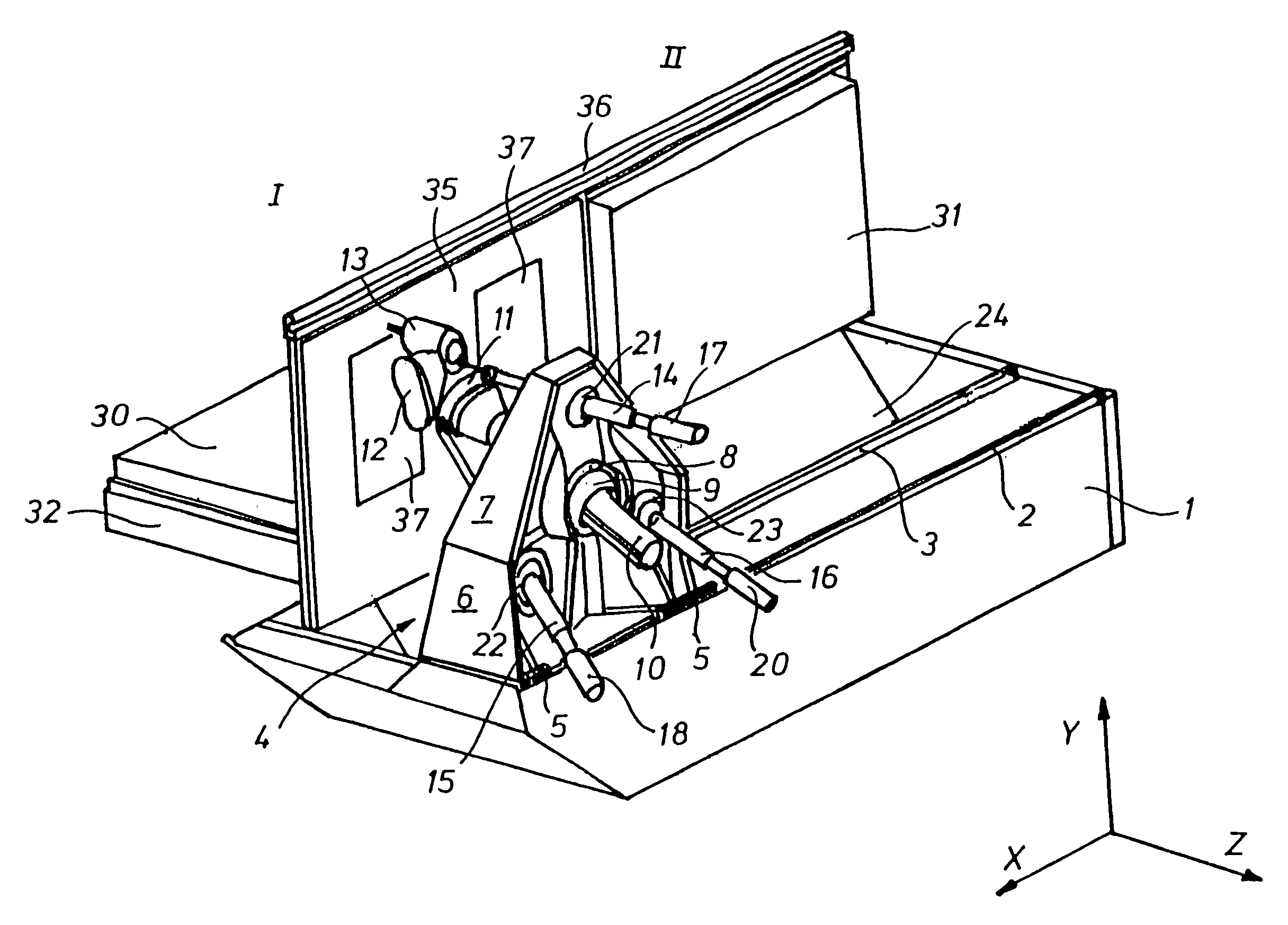
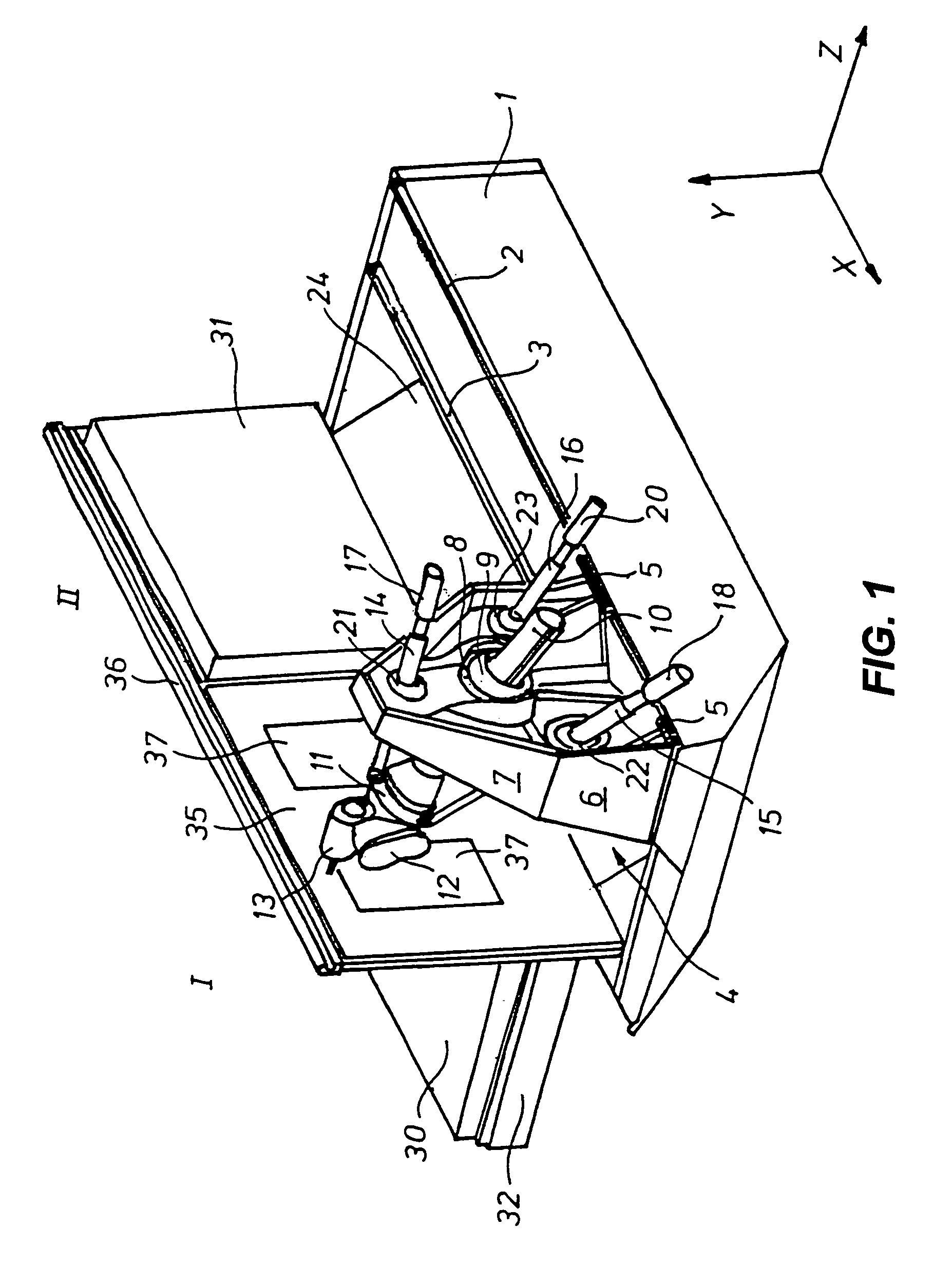
[0015]Referring now to FIG. 1, the machine tool contains relative shallow long bed 1, on the top side of which two guide rails 2 and 3 are mounted. Movable column 4 can be moved on guide rails 2 and 3 by means of a linear drive (not shown), for example, a worm gear or an electric linear motor. This movement can be in the direction of the X-axis defined by the extension of guide rails 2 and 3.

[0016]In a front view, movable column 4 has approximately the shape of a house. It has a relatively wide base provided with guide sockets 5, as well as roof-like upwardly tapering top portion 7. The movable column interior, which is defined by the external walls, contains partition walls and reinforcement ribs so that an altogether highly rigid overall structure results. In approximately the central portion of movable column 4, universal bearing 9 is arranged in recess 8. The recess accommodates, in a longitudinally slidable fashion, dimensionally stable support pipe 10.

[0017]As shown in FIG. 1,...


PUM

PropertyMeasurementUnit
Angleaaaaaaaaaa
Areaaaaaaaaaaa

Abstract

A machine tool for machining large-area workpieces. A column can be moved along one coordinate axis over a long bed. A machining unit, movable at the movable column along at least two other coordinate axes, has a pivotable working spindle. At least one approximately plate-like work carrier can be pivoted from a horizontal set-up position into a vertical machining position. A tripod configuration of the machining unit has a central support pipe and three telescopic legs spaced about 120° with respect to one another. The movable column has, in a central recess, a universal bearing supporting the central support pipe. In each of two lower and one upper recesses a universal bearing for the telescopic legs is provided. A retainer supporting the pivotable working spindle is positioned next to the work area on one end of the central support pipe and is rotatable about an axis of the central support pipe.

Description

BACKROUND OF THE INVENTION[0001]1. Field of the Invention[0002]The present invention relates generally to machine tools, and more specifically to machine tools for machining large area workpieces.[0003]2. Discussion of Related Art[0004]Machine tools or machining centers have been employed for some time to mill and drill large workpieces. They have also been used for large area workpieces commonly found, for example, in automobile or aircraft manufacturing. Generally, each machine tool has two workpiece stations arranged next to one another on the rear side of a long bed and large-area work carriers. They are alternately pivoted from a horizontal set-up position to a vertical operating position. This configuration enables continuous manufacturing. The workpieces in the vertical position can be machined while workpieces already machined can be simultaneously demounted from the horizontally positioned work carrier. Alternatively, new workpieces can be mounted thereon.[0005]In order to ...

Claims


Application Information

Patent Timeline
IPC IPC(8): B23C1/00B23Q11/00B23Q1/00B23Q1/01B23Q1/54B23Q1/58B23Q1/66B23Q11/08B25J17/02
CPCB23Q1/015B23Q1/5462B23Q1/58B23Q1/66B23Q11/08B25J17/0266B25J9/0069B23Q1/545Y10T409/305824Y10T74/20341Y10T409/305264Y10T409/30392Y10T409/309576Y10T409/3056Y10T408/91Y10T409/307672Y10T409/304088
Inventor GRONBACH, HANS
Owner DECKEL MAHO PFRONTEN GMBH
Why Eureka
Try Eureka