Hydraulic balancing magnetically driven centrifugal pump

a centrifugal pump and magnetic drive technology, applied in the field of fluid pumps, can solve the problems of insufficient back side pressure of the valve, inability to provide different impeller sizes, and inherent difficulty in controlling the thrust force with the thrust balancing valve,

Active Publication Date: 2006-09-05
WANNER EGINEERING INC
View PDF19 Cites 43 Cited by
  • Summary
  • Abstract
  • Description
  • Claims
  • Application Information

AI Technical Summary

Benefits of technology

[0015]A still further aspect of the invention relates to a method of balancing a magnetically driven pump that includes a containment shell having a front end and a rear end, a shaft including an internal channel and being fixed to the rear end of the containment shell, a magnetic coupling rotatable about the shaft within the containment shell, front and rear bearings positioned between the magnetic coupling and the shaft that are rotatable relative to the shaft, and a thrust control valve that includes a thrust ring and a valve opening having a size defined by a relative position between the rear bearing and the thrust ring. Steps in the method may include positioning the thrust control valve at the rear of the containment shell between the containment shell and the rear bearing, increasing fluid pressure in the containment shell thereby moving the rear bearing axially away from the thrust ring to increase the size of an opening of the thrust control valve opening, moving the fluid through the valve opening into the internal channel of the shaft thereby decreasing pressure in the containment shell, and moving the rear bearing axially toward the thrust ring as the pressure in the containment shell decreases to balance pressure forces in the pump.

Problems solved by technology

There is an inherent difficulty in controlling the thrust forces with a thrust balancing valve.
These rotating passages contribute to the lack of available pressure at the back side of the valve.
Another problem that is typical for magnetically driven pumps in general is the need to provide different impeller sizes.
Since the impeller is typically permanently attached to the magnet carrier, the cost of the assembly is relatively high.
This means that spare parts or alternate impellers that need to be stocked become a much more expensive inventory.
Even when these components are made separately, they are typically secured together in a manner that is not easily disassembled (e.g., the attachment structure disclosed in U.S. Pat. No. 5,895,203).
Although removable wear rings are described in U.S. Pat. No. 6,234,748, they require separate retainer rings that are not easily removed.

Method used


Image

  • Hydraulic balancing magnetically driven centrifugal pump
  • Hydraulic balancing magnetically driven centrifugal pump
  • Hydraulic balancing magnetically driven centrifugal pump

Examples


Embodiment Construction

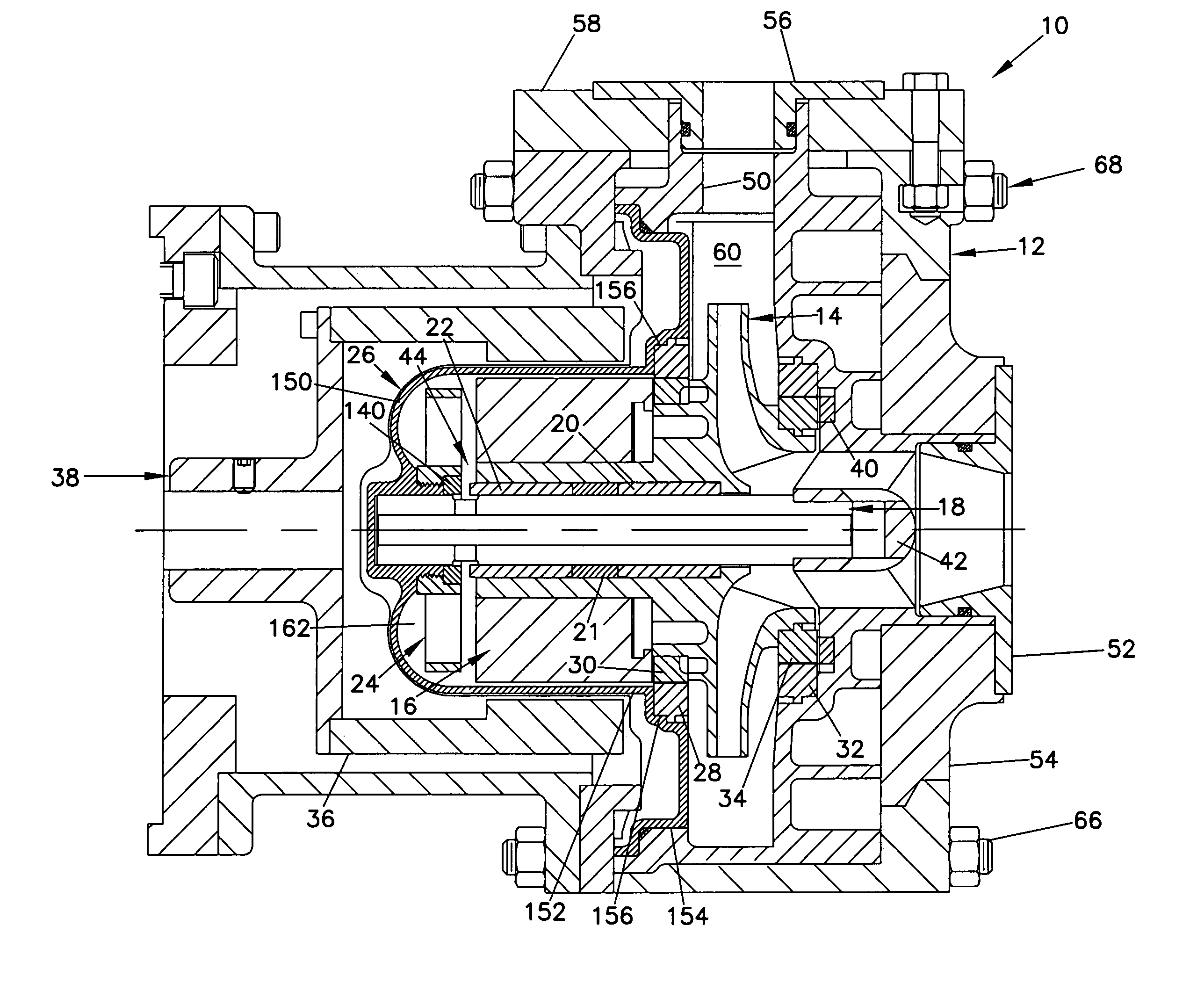
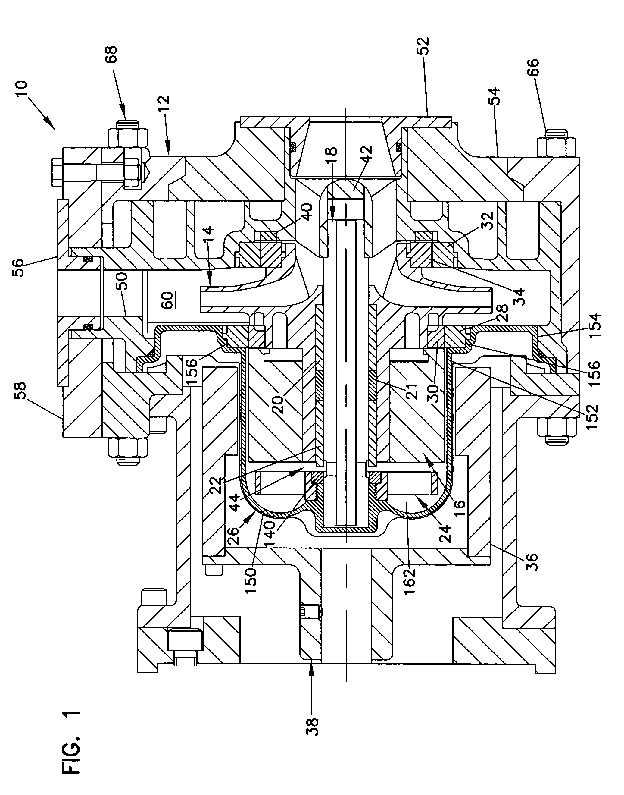
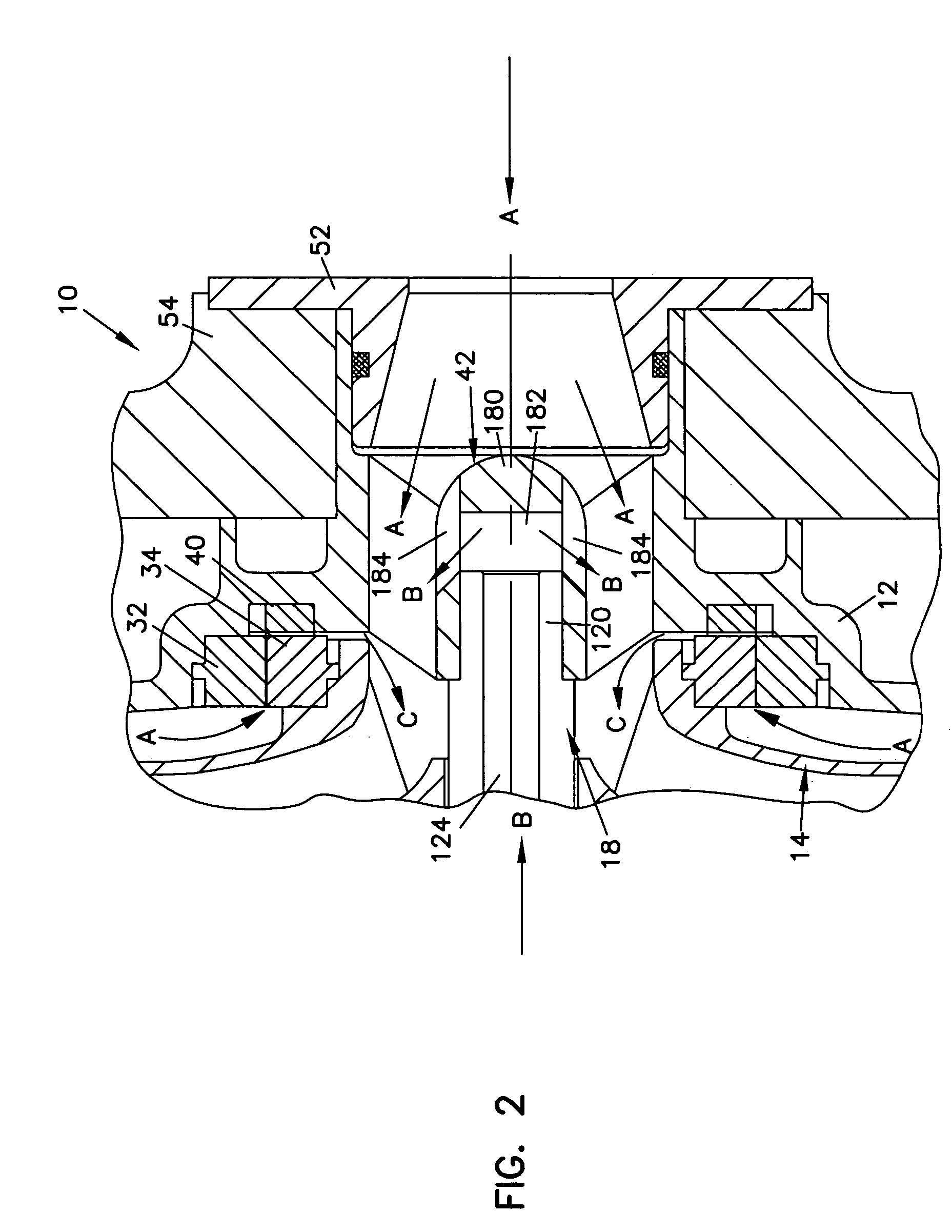
[0028]The present invention generally relates to fluid pumps and more specifically relates to magnetically driven centrifugal pumps. One aspect of the invention relates to a thrust control valve that controls pressure within the pump to balance axial impeller loads. The thrust control valve includes a portion of a rear bearing of the pump and a thrust ring that are located at a closed end of a containment shell of the pump where an end of the shaft is fixed. Fluid passing through the thrust control valve enters a central fluid channel of the shaft and exits the central fluid channel into a primary fluid flow of the pump. Because the shaft maintains a fixed position, the fluid passing through the central fluid channel may travel without rotating, thus increasing the pressure differential across the thrust control valve.

[0029]Another aspect of the invention relates to a stator that includes a plurality of static radial vanes positioned in an inner volume of the containment shell near ...


PUM


Abstract

A magnetically driven pump includes a casing, a containment shell fixed to the casing, a shaft fixed at a closed end of the containment shell, an impeller rotatable about the shaft within the casing and containment shell, and a magnetic coupling removably secured to the impeller and rotatable about the shaft. The pump also includes a rear bearing positioned between the propeller and the shaft that is rotatable about the shaft, and a thrust control valve that includes a thrust ring positioned between the containment shell and the rear bearing. An opening of the thrust control valve is defined by a variable spacing between the thrust ring and the rear bearing.

Description

BACKGROUND OF THE INVENTION[0001]1. Field of the Invention[0002]The present invention generally relates to fluid pumps and more specifically relates to magnetically driven centrifugal pumps.[0003]2. Related Art[0004]Magnetically driven centrifugal pumps are well suited for pumping corrosive or hazardous fluids because they do not have shaft seals that can leak or wear out. Pumps of this type require some method of opposing the thrust load that is created by the impeller. Typically this load is taken by an axial bearing as described in U.S. Pat. No. 4,226,574. To accommodate periodic load opposite to the normal direction that occur in certain pumping conditions, an additional axial bearing containment shell be used as described in U.S. Pat. No. 6,443,710. Another method of opposing these axial loads is by using a thrust balancing system such as that described in by Klein in U.S. Pat. No. 6,135,728. Klein uses fluid pressure to balance the thrust forces and controls the fluid pressure...

Claims


Application Information

Patent Timeline
Patent Type & Authority Patents(United States)
IPC IPC(8): F04B17/00F04D13/02F04D29/04
CPCF04D29/041F04D13/027F04D13/026F04D13/025F04D29/0416H02K5/128H02K7/14
Inventor HEMBREE, RICHARD D.DUPUIS, FRANCIS
Owner WANNER EGINEERING INC
Why Eureka
Try Eureka