Medical manipulator having a plurality of joints

a technology of manipulators and joints, applied in the field of manipulators, can solve the problems of shortened wire life, inability of joints to perform oscillating or swinging operations, etc., and achieve the effects of easy attachment/detachment, small size, and rich controllability

Active Publication Date: 2006-09-05
HITACHI LTD
View PDF7 Cites 167 Cited by
  • Summary
  • Abstract
  • Description
  • Claims
  • Application Information

AI Technical Summary

Benefits of technology

[0005]According to the present invention, being achieved by taking the drawbacks of the conventional arts into the consideration, an object thereof is to provide a manipulator for medical application or

Problems solved by technology

However, with such a configuration in which the opening/closing of the manipulator or the surgical tool is driven using the wires, the routes of the wires are changed when an angle of the joint is varied, and there is a risk that the joint c

Method used


Image

  • Medical manipulator having a plurality of joints
  • Medical manipulator having a plurality of joints
  • Medical manipulator having a plurality of joints

Examples


Embodiment Construction

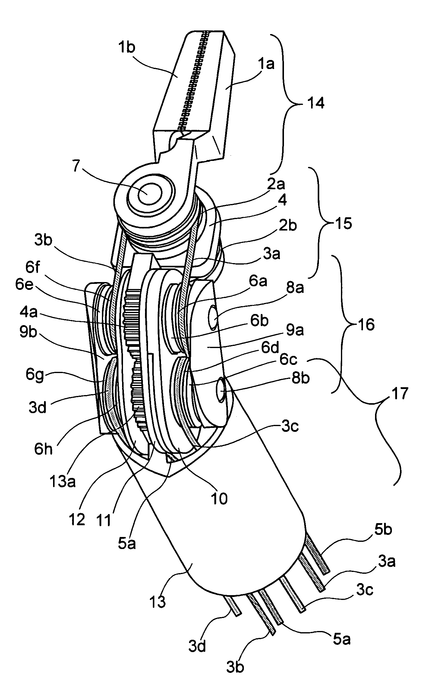
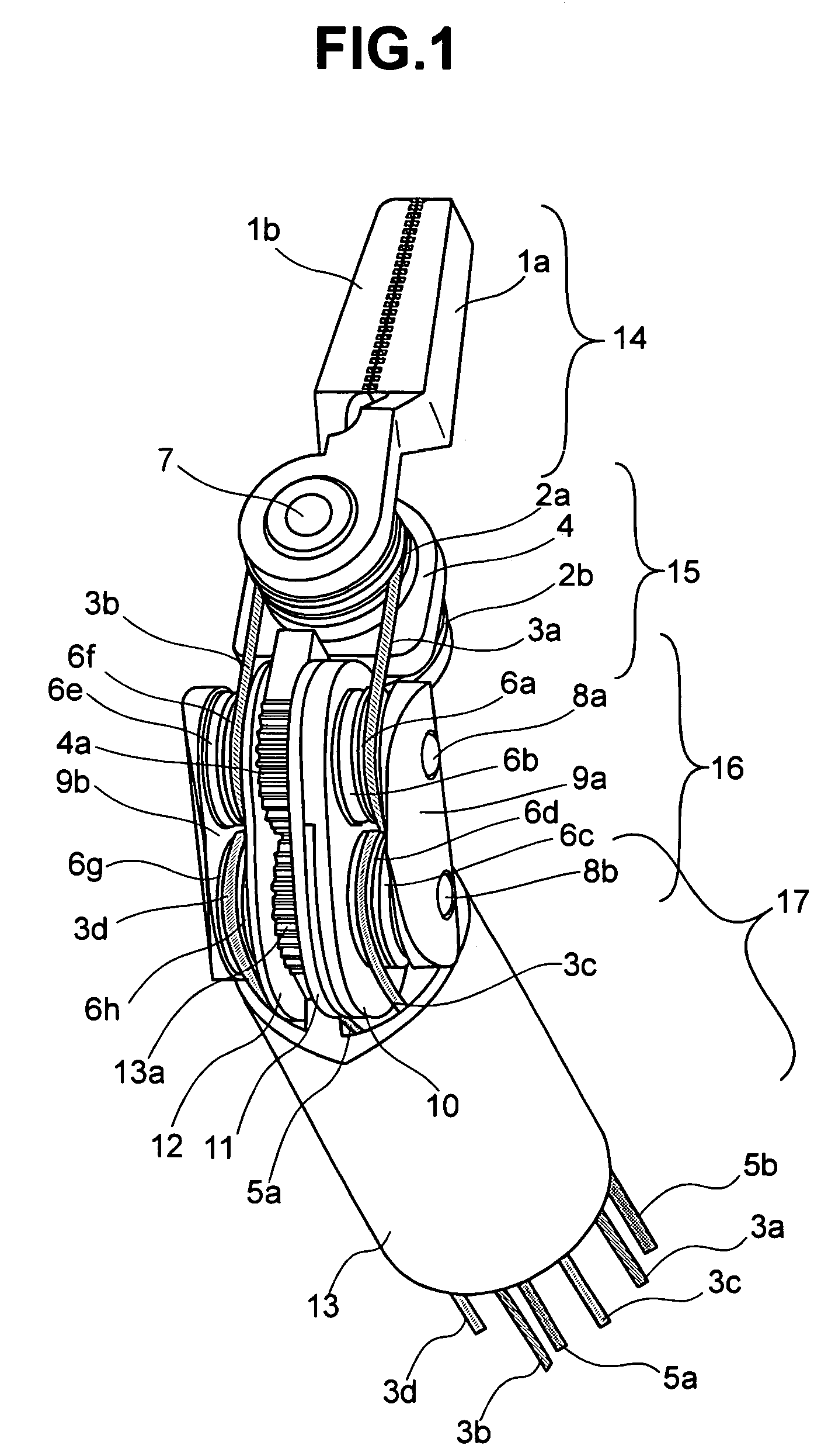
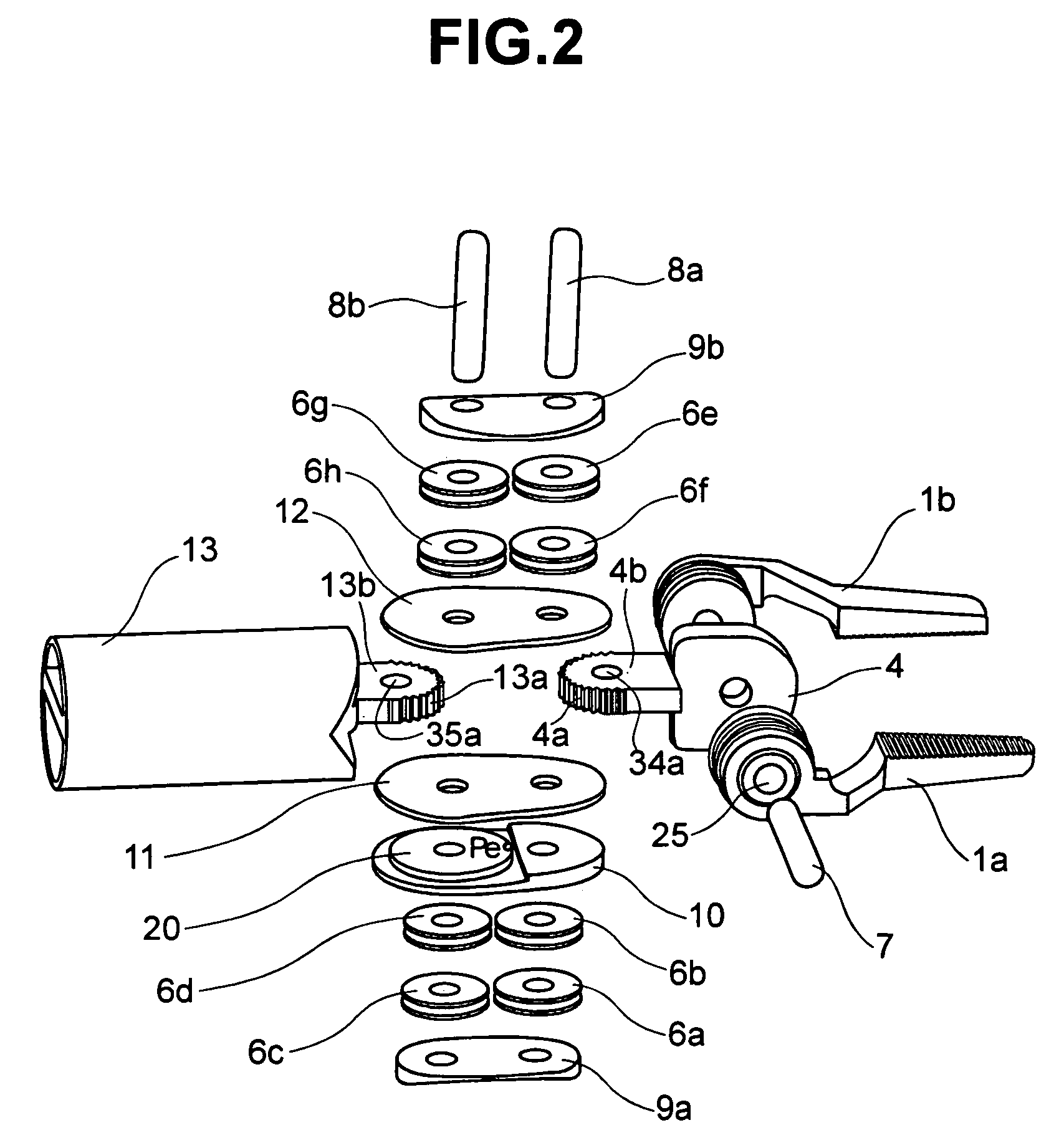
[0025]Hereinafter, embodiments according to the present invention will be fully explained by referring to the attached drawings. Herein, FIG. 1 is a perspective view of a tip portion of a manipulator, and FIG. 2 is an exploded and perspective view of a joint portion of the manipulator shown in FIG. 1. In FIG. 2, blades and wires for driving the oscillation thereof are omitted, for easy understanding. FIGS. 3(A) and 3(B) show the conditions where the joint is in straight and is bent, for explaining the wiring condition of wires. FIG. 4 is a detailed perspective view of a surgical tool at a tip portion of the manipulator, and FIG. 8 is a perspective view for explaining the wiring condition of wires at the actuator side.

[0026]With the embodiment, which will be mentioned hereinafter, explanation will be given on an example, in particular, a manipulator to be used for a medical or clinical purpose. The manipulator for medical use has a grip or hold portion 14 for gripping or holding a se...


PUM


Abstract

A manipulator for medical use having a reduced size and improved controllability. The manipulator includes a surgical tool portion, a grip portion provided on the surgical tool portion, and a driver portion for driving the grip portion provided on the surgical tool portion. A connection portion of the surgical tool is provided between the surgical tool portion and the driver portion. The surgical tool can be separated from, and connected to, the driver portion. The surgical tool portion has two rotating members disposed in opposing relation to each other. A driving arrangement is provided for driving one of the rotating members and causing it to revolute the other rotating member, but not rotate by itself. An arrangement is also provided for keeping a distance between rotation centers of the two rotating members constant.

Description

BACKGROUND OF THE INVENTION[0001]The present invention relates to a manipulator, and in particular, to a manipulator being suitable for use in medical applications.[0002]The manipulators relating to the conventional arts are shown, for example, in U.S. Pat. No. 5,797,900 (Patent Document 1) and U.S. Pat. No. 6,394,998 (Patent Document 2). The manipulator for medical application described in Patent Document 1, uses wires for moving a wrist joint. The position of an actuator, which drives a surgical instrument locating at the tip of the manipulator, is controlled depending on changes in route lengths of the wires. Namely, since the route lengths of the wire change on an inside and an outside of the joint when a first joint is moved on the actuator side, then with using the wires for moving a second joint on the anti-actuator side, also drives the first joint. Also with the Patent Document 2, a joint at a tip portion of a manipulator for medical application, and also a surgical tool pr...

Claims


Application Information

Patent Timeline
IPC IPC(8): A61B17/00A61B17/28A61B17/42A61B17/44B25J17/00A61B17/04A61B19/00B25J7/00B25J17/02
CPCA61B17/062A61B19/22A61B2019/464A61B2017/2939A61B2019/2242A61B2017/2927A61B34/70A61B34/71A61B2090/064
Inventor NISHIZAWA, KOUJITAJIMA, FUJIOKISHI, KOSUKE
Owner HITACHI LTD
Why Eureka
Try Eureka