
Method for detecting slip in generator and starter-generator systems

Inactive Publication Date: 2006-09-05
SEG AUTOMOTIVE GERMANY GMBH
View PDF3 Cites 3 Cited by
  • Summary
  • Abstract
  • Description
  • Claims
  • Application Information

AI Technical Summary

Benefits of technology

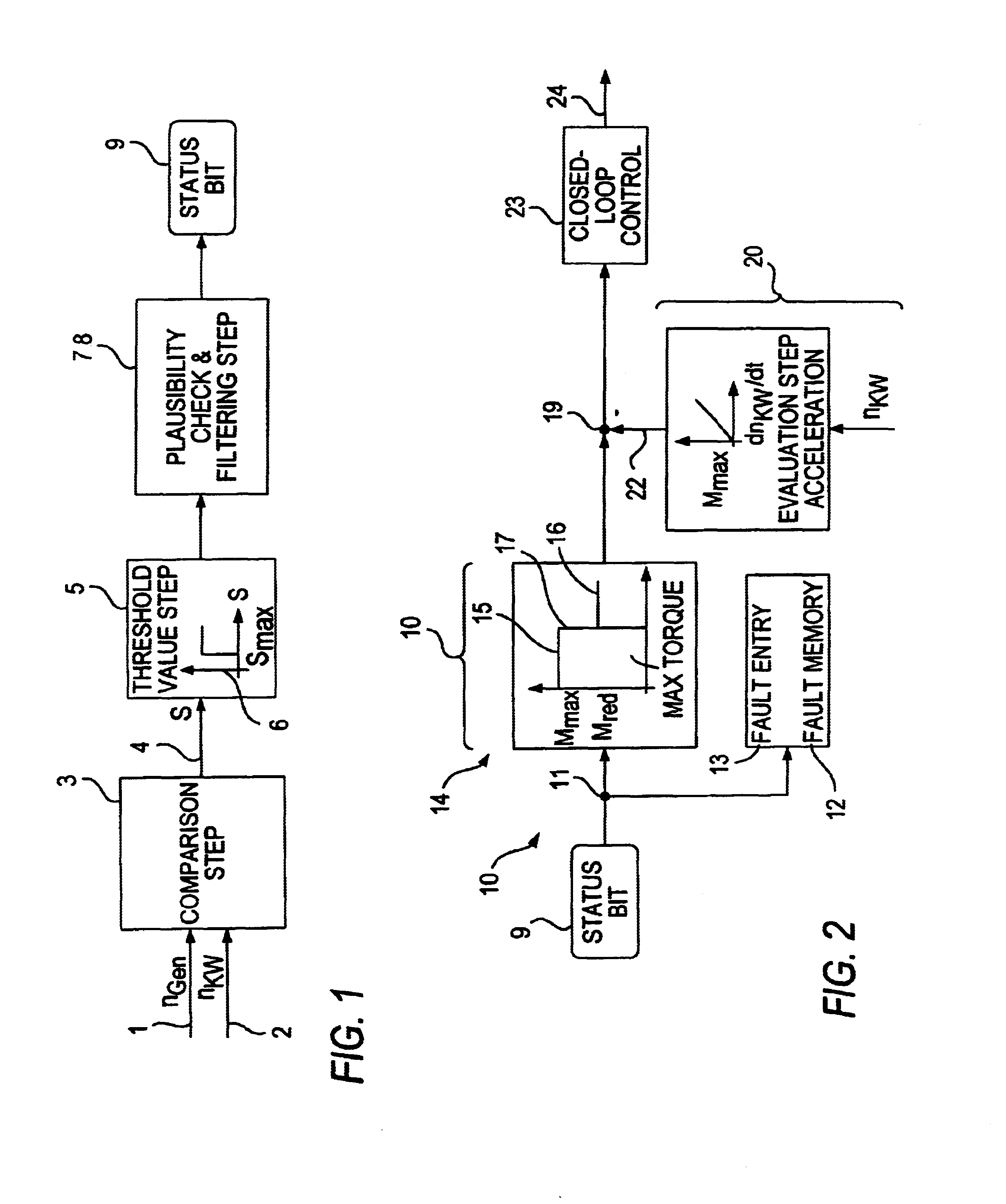
[0006]By means of the method proposed according to the invention, the service life of a belt drive can be extended significantly, and the high levels of noise emissions that occur between the belt and the belt pulley driving the alternator when slip is present are reliably prevented. This is obtained by the fact that the generator output power is reduced during an operating phase of the motor vehicle—which is characterized by high speed dynamics, for example—and, as a result, the drive torque to be applied on the drive side of the alternator decreases. Additionally, the generator output power is reduced via the alternator closed-loop control when the instantaneous value of the slip s exceeds the maximum permissible slip value smax.
[0007]If an instantaneous slip s that exceeds the maximum slip value smax is detected, an initial reduction of the maximum permissible drive torque of the alternator takes place by limiting the generator output power. If an acceleration phase of the internal combustion engine also occurs during this operating phase, its rotational speed also increases greatly, [and] the maximum permissible, reduced drive torque for the alternator determined in the first limiting step can be reduced once more by means of a further limiting step. In particular, this inhibits a noise emission occuring in acceleration phases when a belt slips through and that is perceived as very unpleasant.

Problems solved by technology

In particular, this inhibits a noise emission occuring in acceleration phases when a belt slips through and that is perceived as very unpleasant.

Method used


Image

  • Method for detecting slip in generator and starter-generator systems
  • Method for detecting slip in generator and starter-generator systems
  • Method for detecting slip in generator and starter-generator systems

Examples


Embodiment Construction

[0014]FIG. 1 shows the generation of a status bit that displays the occurrence of slip and that is capable of being processed further.

[0015]As indicated in the illustration according to FIG. 1, two input variables 1, 2 are forwarded to a comparison step 3. Input variable 1 represents the rotational speed of the alternator nGen. Input variable 2 represents the instantaneous crankshaft rotational speed nKW of the internal combustion engine that drives the alternator. Input variable 2 is picked off by a communication interface of the vehicle electronics and it is picked off in cyclic fashion by a speed sensor, so that instantaneous value of the rotational speed of the internal combustion engine present at the comparison step 3 is always current. In the comparison step shown in FIG. 1 as a schematic representation only, the actual instantaneous slip value 4 s is calculated according to the relationship: (nkw·u¨-nGen)nkw·u¨=s

with ü=pulley ratio.

[0016]The output value for the instantaneou...


PUM


Abstract

The invention is based on a method for detecting slip in the driving of generator or starter-generator systems. The alternators of these systems are equipped with electronic control components such as pulse-width-modulated inverters or rectifier bridges. The drive torque of the alternator is transferred to this by means of a belt drive of an internal combustion engine. When slip is detected in a comparison step (3), to which speed-dependent input variables (1, 2) are forwarded, the maximum transferrable drive torque is determined in a torque limiting step (18, 20), and a closed-loop control (23) adjusts the generator output power to said maximum transferrable drive torque.

Description

TECHNICAL BACKGROUND[0001]Alternators installed in motor vehicles are driven directly by the vehicle engine. The driving is generally realized with belt drives. High requirements in terms of force transmission are placed on belt drives, whether they are V-belts or ribbed V-belts. The belt material must have extensive bending strength. Moreover, the linear extensional strain over the course of ageing must be as minimal as possible in order to prevent slip—combined with excessive heating-up and wear—of the belt.BACKGROUND OF THE INVENTION[0002]Alternators that are driven via normal V-belts by the internal combustion engine are secured almost exclusively with a swivel arm. If the swivel arm is situated such that it can turn around a rocker pivot, the V-belt tension can be readjusted and retensioned accordingly by swiveling the generator if the belt becomes stretched. The V-belt is usually readjusted at certain inspection intervals or when the V-belt can be heard slipping on the belt pu...

Claims


Application Information

Patent Timeline
Patent Type & Authority Patents(United States)
IPC IPC(8): H02P9/00F02B67/06H02P9/04F02N11/04F02N15/02F02N15/10H02P9/02
CPCF02B67/06F02N11/04H02P9/02F02N15/10F02N15/025
Inventor SCHERRBACHER, KLAUSBECK, MARKUS
Owner SEG AUTOMOTIVE GERMANY GMBH
Learn More