Cantilever rear suspension for a bicycle

a rear suspension and bicycle technology, applied in the field of bicycles, can solve the problems of no prior art suspension system meeting all of these goals, system is heavy, complex or requires frequent maintenance, etc., and achieves the effects of reducing unwanted play, reducing biopacing or pogoing, and extending the service li

Active Publication Date: 2006-09-12
GINGL MANFRED
View PDF21 Cites 49 Cited by
  • Summary
  • Abstract
  • Description
  • Claims
  • Application Information

AI Technical Summary

Benefits of technology

[0009]The invention may provide a number of desirable characteristics. For example, the bearings for the swing arm have a single pivot point and may have a large surface area. This tends to reduce unwanted play, particularly after extended use. Since the rotation axis of the trailing arm is coaxial with the crank axis, the chain length required to connect the front and rear sprockets remains constant regardless of the position of the rear suspension.

Problems solved by technology

These types of bikes are often used in rough terrain, leading to an uncomfortable ride.
However, no prior art suspension system meets all of these goals.
Some systems are heavy, complex or require frequent maintenance.
Some systems also cause adverse effects on other parts of the bicycle.
Some systems also create undesired reactions.
These systems are generally complex and therefore expensive to manufacture.
They also are subject to wear in multiple locations.
These pivot points add si

Method used


Image

  • Cantilever rear suspension for a bicycle
  • Cantilever rear suspension for a bicycle
  • Cantilever rear suspension for a bicycle

Examples


Embodiment Construction

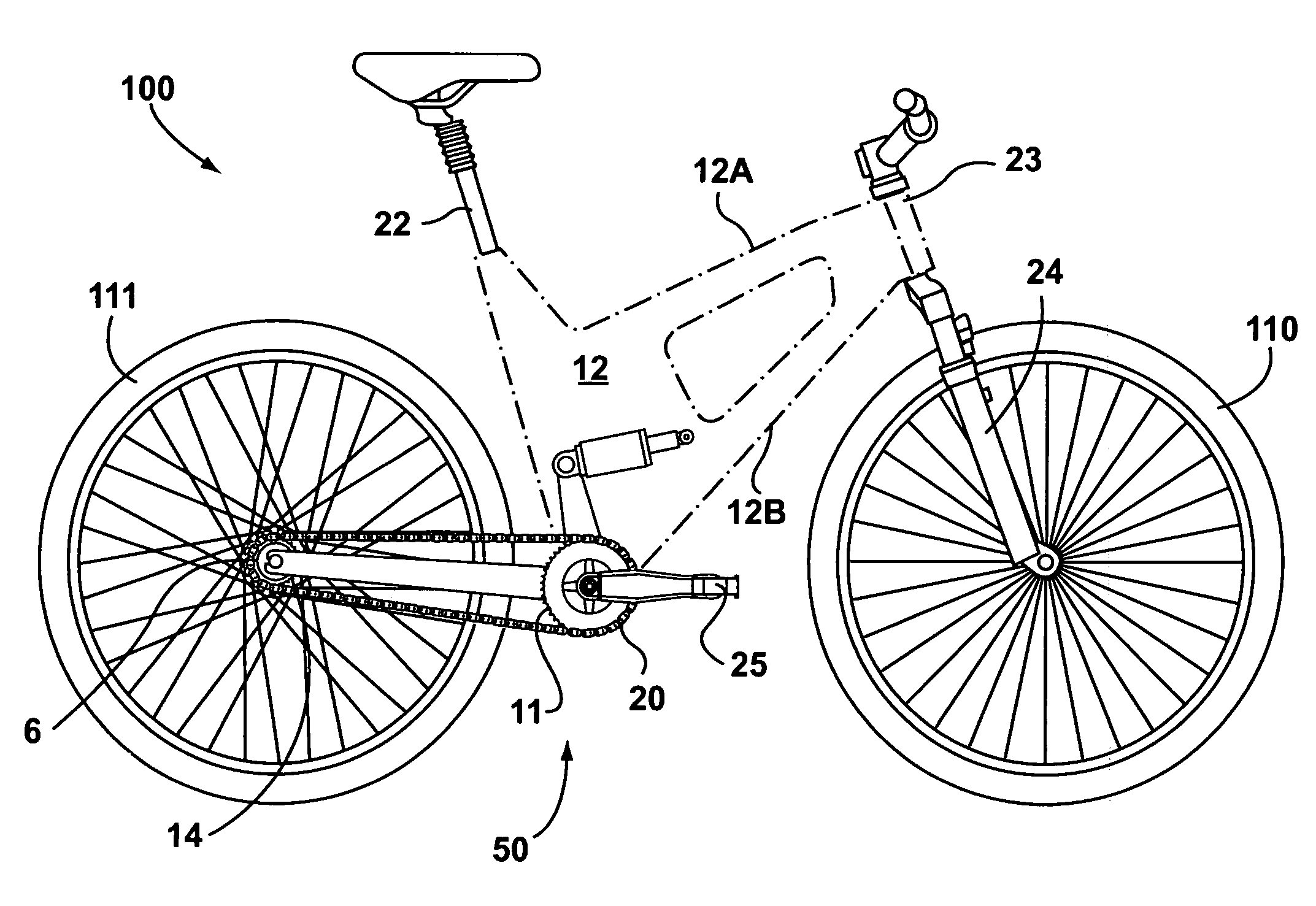
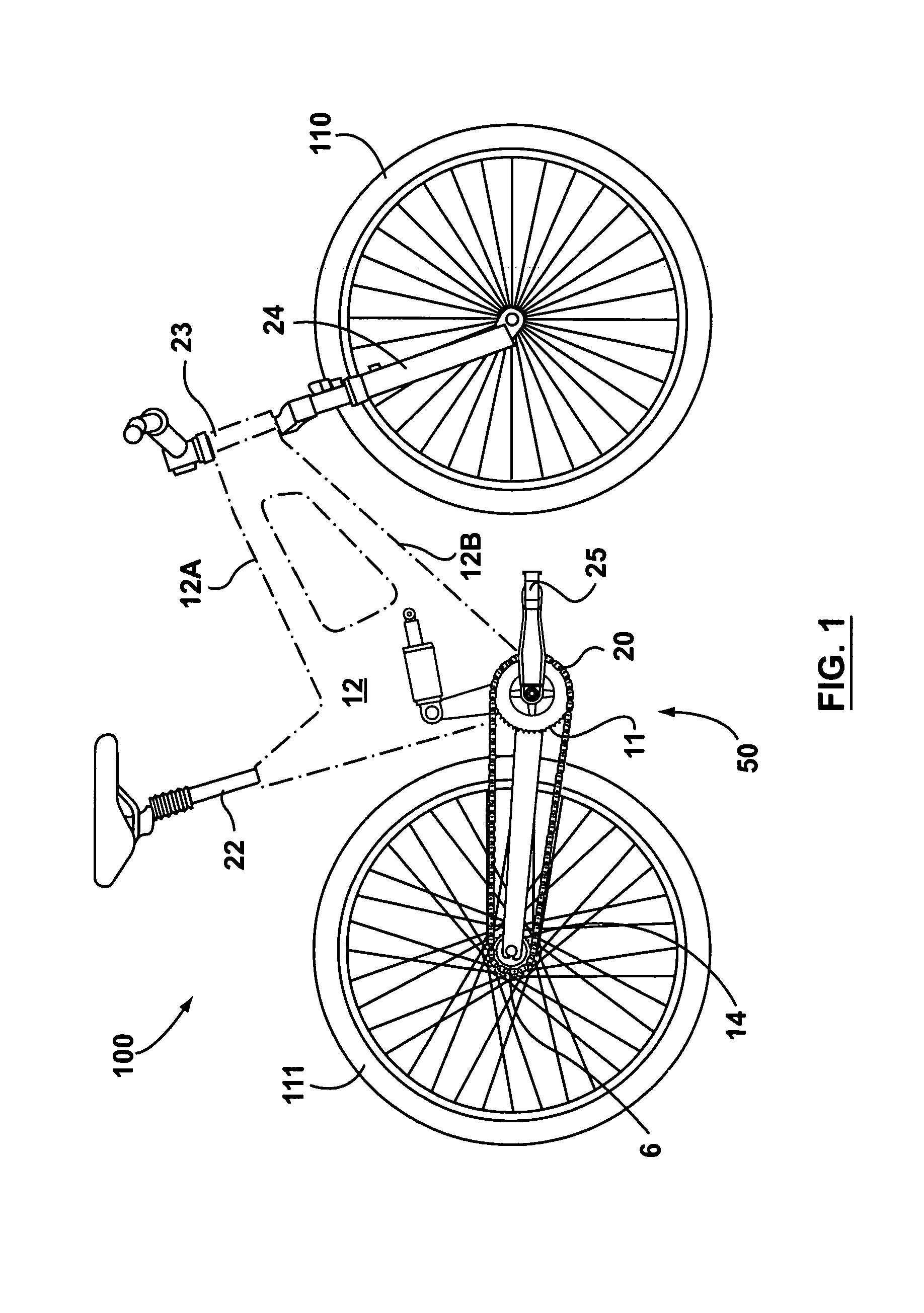
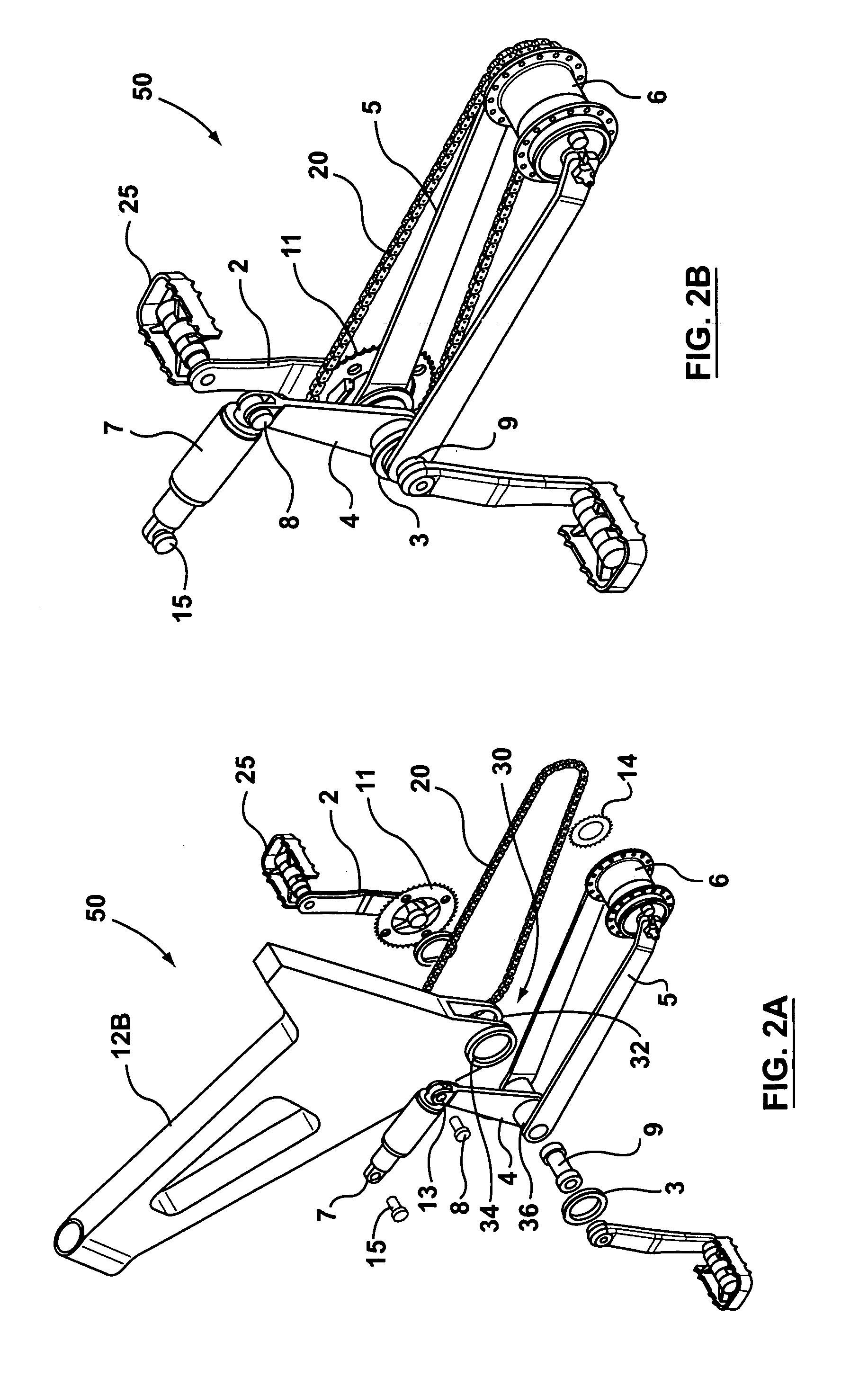
[0033]FIG. 1 shows a bicycle 100 according to an embodiment of the invention, comprising a main frame indicated in its entirety by the reference number 12. The frame 12 may have a top frame part 12A and a bottom frame part 12B. The frame 12 has two sides which include stressed walls of a monocoque or semi-monocoque shell, although other frame designs may also be used. The frame 12 supports a saddle-bearing tube or seat post 22, an attachment or head tube 23 for the handlebars and a fork 24 to which the front wheel 110 is associated in a conventional manner. The frame 12 is part of a suspension assembly 50 which supports the rear wheel 111. A transmission assembly is of the conventional chain and sprocket type, whereby rotary motion from the pedals 25, acting through crank arms 2, is transmitted to the rear wheel 111 via a chain 20 that is wrapped around a front sprocket 11 and rear sprocket 14, more clearly visible in FIGS. 2A and 2B.

[0034]The various components of the suspension as...


PUM


Abstract

A bicycle is equipped with a rear wheel suspension having a swing arm with one or more generally cantilevered side arms, which are capable of withstanding bending and torsional loads and isolating said loads from the rider. A bottom portion of the bicycle frame includes a pedal sleeve. A pedal or crank assembly rotates within the pedal sleeve about a rotational axis with a fixed location relative to the frame. The swing arm is pivotally secured to the frame for movement about the rotational axis. A shock-absorbing element is connected between the swing arm and the frame.

Description

[0001]This patent claims the benefit under 35 USC 119(e) of U.S. Provisional Application Ser. No. 60 / 457,626 filed Mar. 26, 2003, which is incorporated in full herein by this reference to it.FIELD OF THE INVENTION[0002]The subject invention is generally related to bicycles, and is specifically related to a rear suspension system for a bicycle.BACKGROUND OF THE INVENTION[0003]Bicycles have been utilized as a means of transportation for over a hundred years and continue to grow in popularity. The mountain bike is one type of bike that has become more and more popular in recent years. These types of bikes are often used in rough terrain, leading to an uncomfortable ride. Therefore, some recently designed bicycle frames include a rear suspension system. Bicycles equipped with suspension attempt to provide increased rider comfort, enhanced wheel contact and control, and less net rolling resistance without significantly increasing the cost, complexity or maintenance requirements of the bi...

Claims


Application Information

Patent Timeline
IPC IPC(8): B62K25/28B62K25/30
CPCB62K25/30
Inventor SCHMIDER, JOHNVENIER, FABIO
Owner GINGL MANFRED
Why Eureka
Try Eureka