Windbreaker air drag reduction system

Inactive Publication Date: 2006-09-12
SANNS RANDY A
View PDF16 Cites 21 Cited by
  • Summary
  • Abstract
  • Description
  • Claims
  • Application Information

AI Technical Summary

Benefits of technology

[0003]The present invention represents an improvement over the prior art, in that a comparatively simple, wedge-shaped fairing element is provided for mounting on the forward face of a blunt-nosed, or flat-nosed, vehicular trailer. The wedge-shaped fairing element is provided with an angular, rearwardly extending surface which is contoured for the deflection of impinging air streams from head on, quartering, and crosswise directions, to thereby substantially reduce air resistance on the trailer and to substantially improve its handling characteristics. In addition, the apparatus of the present invention is adapted for ready and facile mounting with simple fastening means, such as application by conventional clamps, brackets and screws, requiring minimal modification to the towed vehicle.
[0005]Due to its simplified construction, the novel wedge-shaped fairing element of the present invention may be packaged for shipment to an installer with a minimum number of parts, and a simplified array of conventional obtainable components for installation using conventional fastening means.

Problems solved by technology

Obviously, this requires a substantial modification to the trailer or similar blunt-nosed towed vehicle.
Other prior art devices, although successful in varying degrees in reducing the aerodynamic resistance or drag on a vehicle, are deficient to the extent that they require either substantial modification to the towed vehicle to employ the devices, or necessitate use of a combination of several devices to achieve reduction of aerodynamic resistance in both the head flow and cross flow of air.
The other prior art devices substantially increase the cost of air resistance reduction.

Method used


Image

  • Windbreaker air drag reduction system
  • Windbreaker air drag reduction system
  • Windbreaker air drag reduction system

Examples


Embodiment Construction

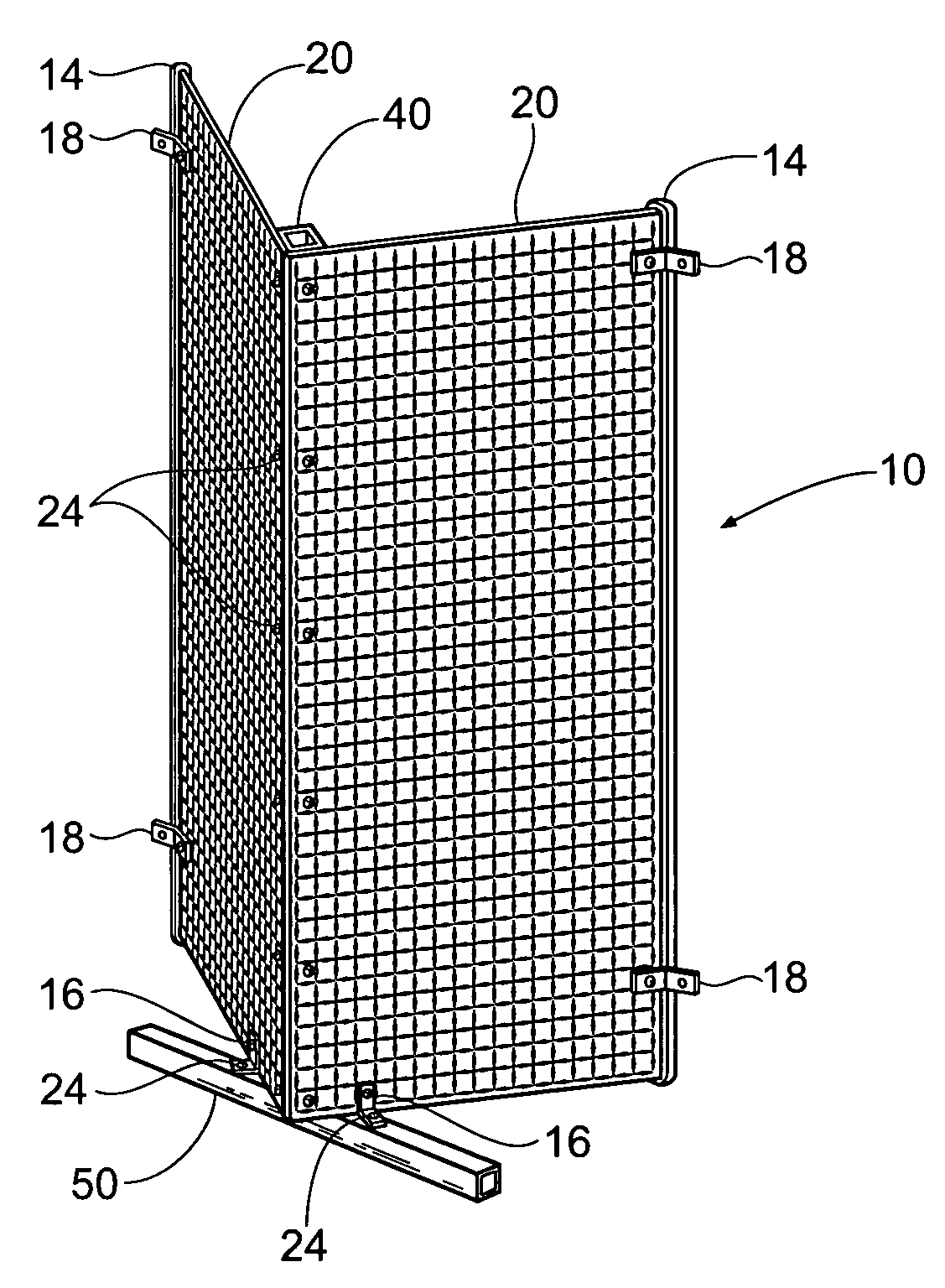
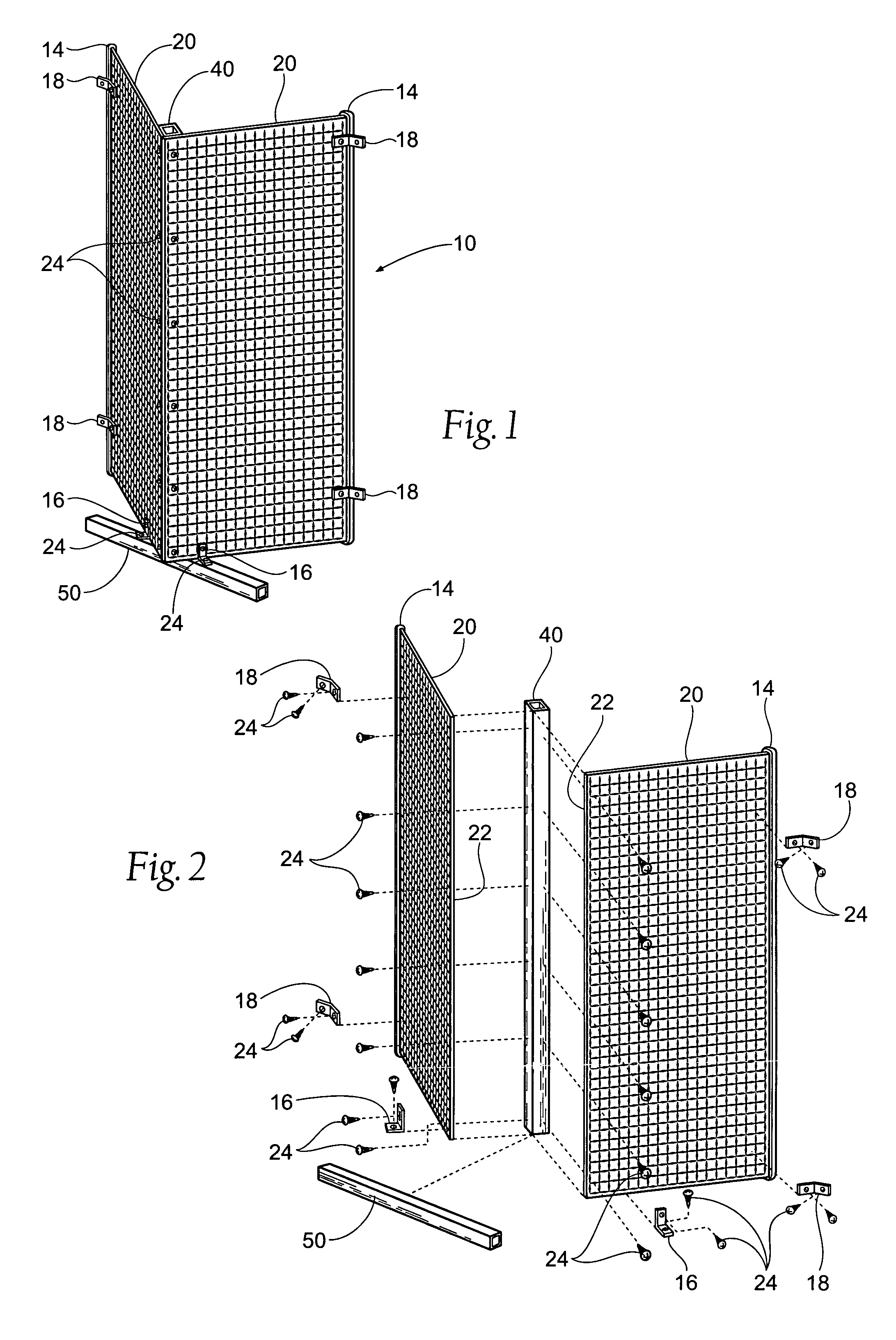
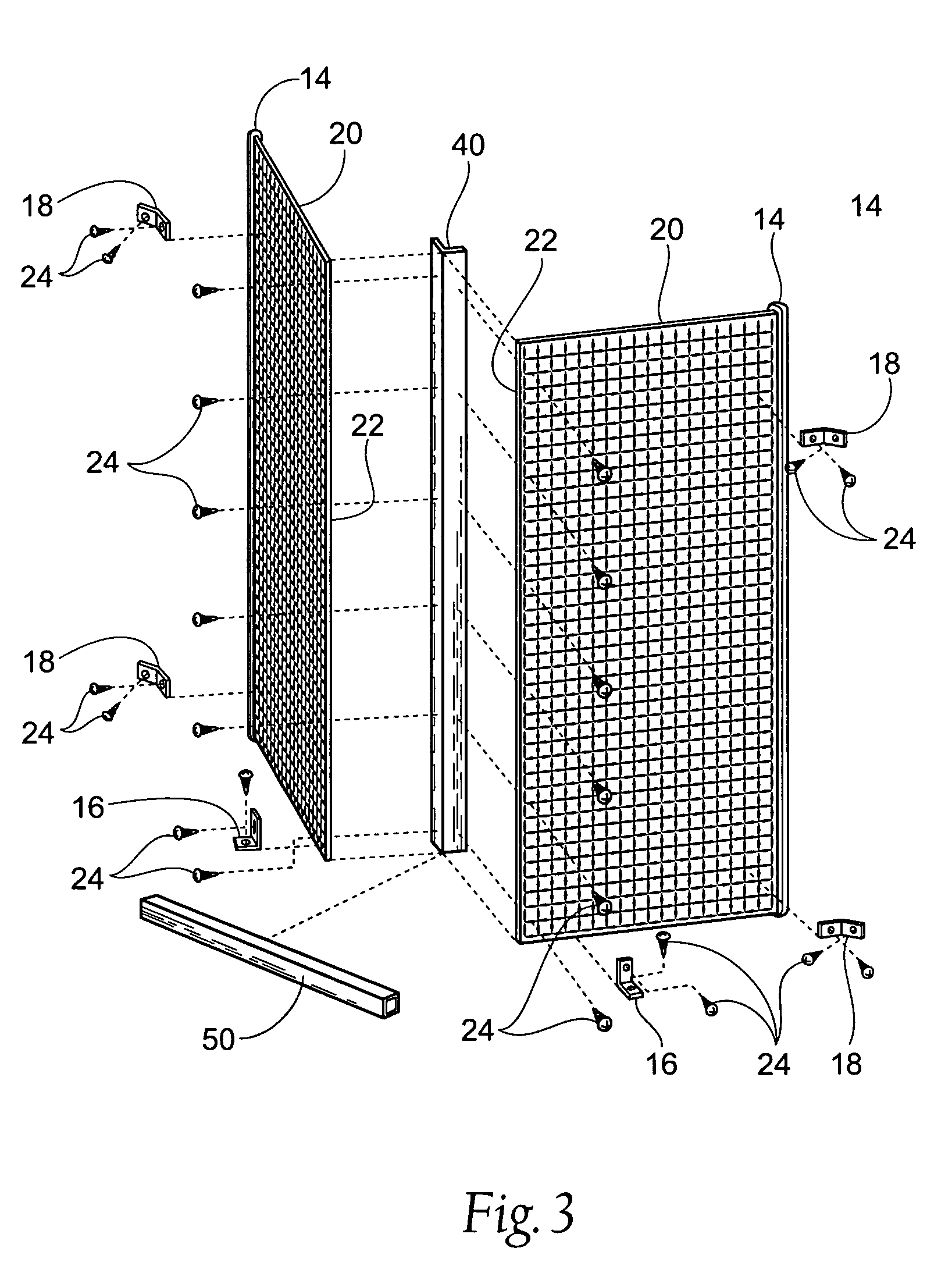
[0011]As shown in the drawings, the present invention is embodied in a wedge-shaped fairing element 10 which is adapted to be mounted on and secured to a blunt-nosed towed vehicle, such as a trailer 70 (see FIG. 4). When mounted, the wedge-shaped fairing element 10 is adapted for modifying the flow of air during operation of the trailer 70 thereby substantially reducing the aerodynamic drag and improving the handling characteristics of the trailer 70.

[0012]With particular attention to FIG. 4, it will be observed that the wedge-shaped fairing element 10 is preferably mounted on the blunt-nosed, forward face 12 of a conventional towed vehicle or trailer 70.

[0013]As illustrated in FIG. 4, the trailer 70 includes a conventional forward-extending hitching tongue 80. The hitching tongue 80 is composed of bifurcated, angularly extending support beams 82A and 82B, each terminating in a triangular apex 84 which is further formed with a conventional releasable hooded element 85. The hooded el...


PUM


Abstract

A windbreaker air drag reduction system for trailers and other box-like towed vehicles having a blunt-nosed forward face. The system comprises a wedge-shaped fairing element including a pair of upstanding panel members adjoining one another and being secured to an upstanding riser. The panel members and riser are attached to a crossbar member which is securely clamped to the trailer tongue support beams. The panel members are secured to the upper and lower face of forward face of the trailer at their respective outward edges. The combined components of the fairing element cooperate to form a triangular arrangement, the apex of the triangle being located forwardly of the blunt-nosed forward face of the vehicle. The entire system may be attached, detached, and reattached to multiple trailers or towed vehicles by means of simple tools and assembly and ease of use by only one operator.

Description

RELATED APPLICATIONS[0001]This application claims the benefit of co-pending Provisional Patent Application Ser. No. 60 / 596,551, filed on 3 Oct. 2005.BACKGROUND OF THE INVENTION[0002]Various prior art devices have been suggested for reducing aerodynamic drag of a moving vehicle, and more particularly to apparatus for reducing air drag on flat-nosed trailer trucks, railroad cars, and other similar blunt-nosed, towed vehicles which present a substantially broad aerodynamically resistant surface in the direction of travel of the vehicle. Of these prior art devices, there are disclosures of various provision of air vanes or fins around the edges of the cargo carrying portion of the vehicle to deflect the impinging air stream. Such devices include large blister-shaped deflectors provided with an opening for collecting impinging air, and a conduit means extending along the trailer to exit collected air at the rear portion of the trailer. Obviously, this requires a substantial modification ...

Claims


Application Information

Patent Timeline
IPC IPC(8): B60R27/00B60R99/00
CPCB62D35/001
Inventor SANNS, RANDY A.
Owner SANNS RANDY A
Why Eureka
Try Eureka