Lens protection for medical purposes

a technology for protecting lenses and medical purposes, applied in the field of viewing devices, can solve the problems of reducing image quality, time-consuming, risk-increasing, and often uncomfortable procedures, and achieve the effect of preventing inadvertent damage to body tissues

Inactive Publication Date: 2006-09-12
CLEANOSCOPE
View PDF17 Cites 39 Cited by
  • Summary
  • Abstract
  • Description
  • Claims
  • Application Information

AI Technical Summary

Benefits of technology

[0015]An aspect of some embodiments of the present invention relates to a contact-sensitive lens protector. In an exemplary embodiment of the invention, the view-through element stops rotating when it contacts a surface, for example a membrane in the body, for example, to prevent inadvertent damage to body tissues. In an exemplary embodiment of the invention, the lens protector is provided with enough power to generate a torque that can sustain substantially free rotation, but not with enough power to re-start the rotation once it has stopped. In an exemplary embodiment of the invention, a control box includes a restart-button, for sending a power surge to the lens protector, so that it can be restarted.

Problems solved by technology

Various optical systems are required to operate in adverse environments, in which various solid particles and / or fluid droplets etc. and / or other agglomerations of one or more materials of various stickiness or viscosity (herebelow collectively termed “debris”) may adhere to the lens and reduce image quality.
A particularly difficult environment to view is the inside of the human body.
Sometimes the endoscope must be withdrawn for cleaning and reinserted, a time-consuming, risk-increasing and often uncomfortable procedure.

Method used


Image

  • Lens protection for medical purposes
  • Lens protection for medical purposes
  • Lens protection for medical purposes

Examples


Embodiment Construction

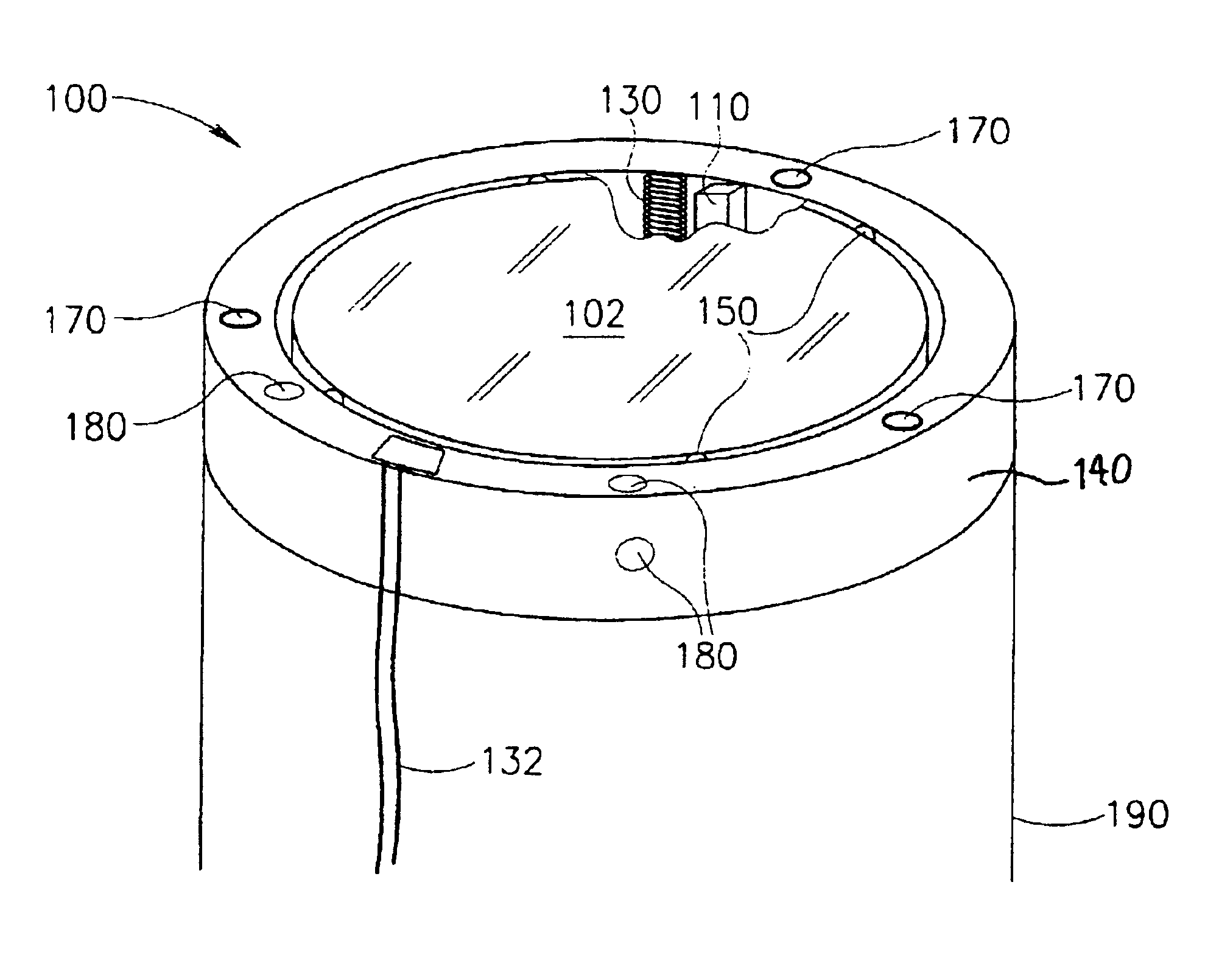
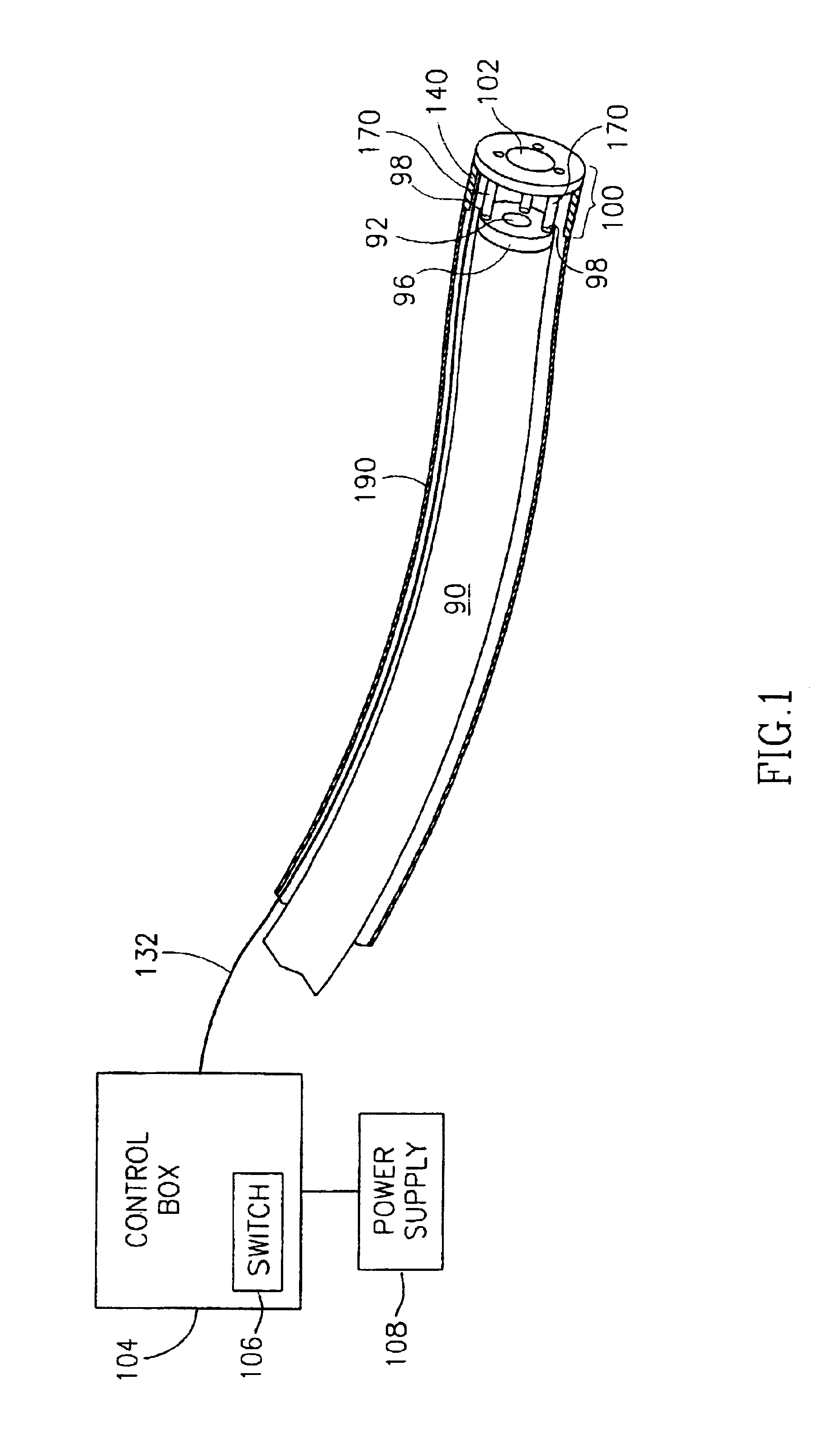
[0038]FIG. 1 is a oblique schematic view of the inserted end of an endoscope 90, with its head covered by a centrifugal lens protector 100, in accordance with some embodiments of the present invention. (The distance between lens protector 100 and the head of endoscope 90 is exaggerated for clarity.)

[0039]At the front of endoscope 90 is a lens 92, held in a housing 96. Optionally one or more tubes 98 pass through housing 96. Tubes 98 may be used for a variety of functions, for example, for pumping gas into the volume to be viewed, to suck fluids and particles out from the volume, to spray water for example to clean an area to be viewed or to clean endoscope lens 92, to provide light, to provide therapeutic materials and / or to provide tools. The sizes and number of tubes 98 may vary between endoscopes. Different lens protectors may be provided for different sized and configured endoscopes.

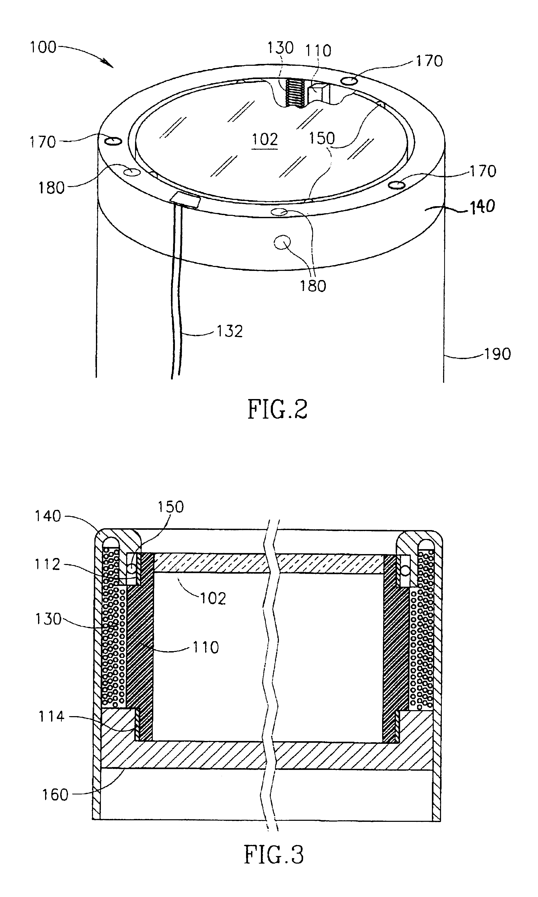
[0040]Lens protector 100 is affixed at the front of endoscope 90. A disc 102 (or a curved plate o...


PUM


Abstract

A low profile medical lens protector (100) for a medical viewing device having a given diameter, comprising: a rotatable view-through element; a motor which rotates said view-through element; and a housing (140) enclosing said view-through element and said motor, characterized in that said housing has an outer diameter less than 10 mm greater than said given diameter.

Description

RELATED APPLICATIONS[0001]This application is a U.S. national filing of PCT Application No. PCT / IL01 / 00158, filed on Feb. 20, 2001. This application is also related to PCT Application No. PCT / IL00 / 00750, filed on Nov. 15, 2000, the disclosure of which is incorporated herein by reference.FIELD OF THE INVENTION[0002]The present invention is related to the field of protection of viewing devices from interference, especially by means of centrifugal lens protectors.BACKGROUND OF THE INVENTION[0003]Various optical systems are required to operate in adverse environments, in which various solid particles and / or fluid droplets etc. and / or other agglomerations of one or more materials of various stickiness or viscosity (herebelow collectively termed “debris”) may adhere to the lens and reduce image quality.[0004]One solution is a centrifugal lens protector, in which a spinning glass disc is placed before the lens, so that all the particles are intercepted by the disc. The centrifugal force ge...

Claims


Application Information

Patent Timeline
Patent Type & Authority Patents(United States)
IPC IPC(8): G03B11/04A61B1/00G03B11/00G03B17/08G03B17/12G03B37/00
CPCG03B11/00G03B17/08G03B17/12A61B1/00096A61B1/00101A61B1/126G03B37/005
Inventor SHERWIN, DANIEL
Owner CLEANOSCOPE
Why Eureka
Try Eureka