Temperature sensor with quick response

a technology of temperature sensor and response characteristic, which is applied in the field of temperature sensor, can solve the problems of difficult to achieve greater improvement of response characteristic, and achieve the effect of preventing the heat of exhaust gas or the like and better response temperature sensor

Active Publication Date: 2006-09-12
NGK SPARK PLUG CO LTD
View PDF11 Cites 19 Cited by
  • Summary
  • Abstract
  • Description
  • Claims
  • Application Information

AI Technical Summary

Benefits of technology

[0009]Therefore, in consideration of the problem, an object of the present invention is to provide a temperature sensor which can achieve higher response characteristic.
[0034]If short-circuiting occurs because the metal tube comes into contact with one of the electrode wires of the thermal sensing element or the electrode wires come into contact with each other, the temperature cannot be detected. Therefore, it is necessary to hold the electrode wires of the thermal sensing element in the inside of the metal tube so that the metal tube can be prevented from coming into contact with one of the electrode wires or the electrodes can be prevented from coming into contact with each other. On the other hand, to improve response characteristic of the temperature sensor, it is necessary to store the thermal sensing portion in the small-diameter portion of the metal tube. Therefore, the temperature sensor according to the invention is designed so that all regions of the pair of electrode wires of the thermal sensing element located on the rear end side viewed from the rear end of the thermal sensing portion are disposed in the large-diameter portion of the metal tube. Because all regions of the pair of electrode wires of the thermal sensing element located on the rear end side viewed from the rear end of the thermal sensing portion are disposed in the large-diameter portion of the metal tube as described above, the distance between the metal tube and each of the electrode wires can be secured. Accordingly, the distance between the electrode wires, the distance between the metal tube and each of the metal cores and the distance between the metal cores can be secured. For this reason, there can be provided a temperature sensor in which the thermal sensing portion is stored in the small-diameter portion of the metal tube so that electric insulation between the metal tube and each of the electrode wires and between the metal tube and each of the metal cores and electric insulation between the electrode wires and between the metal cores are secured while response characteristic of the temperature sensor is secured.

Problems solved by technology

For this reason, it is difficult to attain greater improvement of response characteristic in the temperature sensor having such a structure.
For this reason, also in the temperature sensor having such a structure, it is difficult to attain greater improvement of response characteristic.

Method used


Image

  • Temperature sensor with quick response
  • Temperature sensor with quick response
  • Temperature sensor with quick response

Examples


embodiment 1

(Embodiment 1)

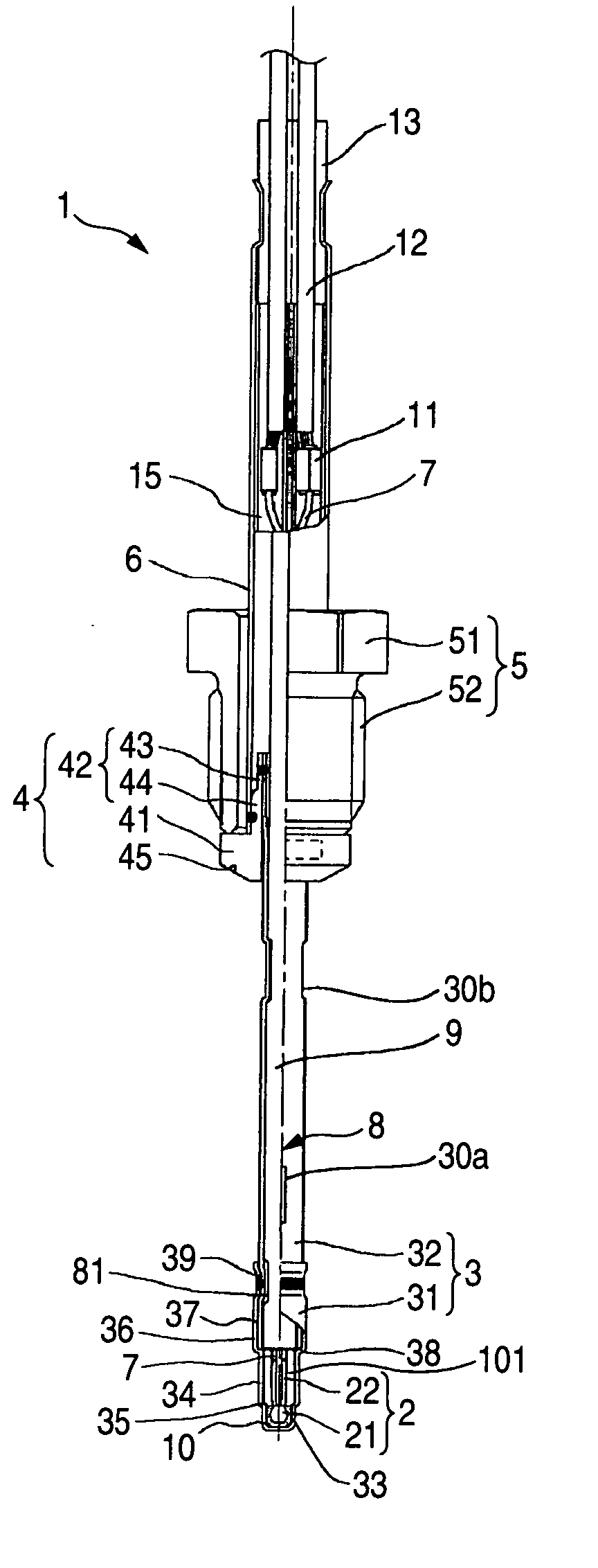
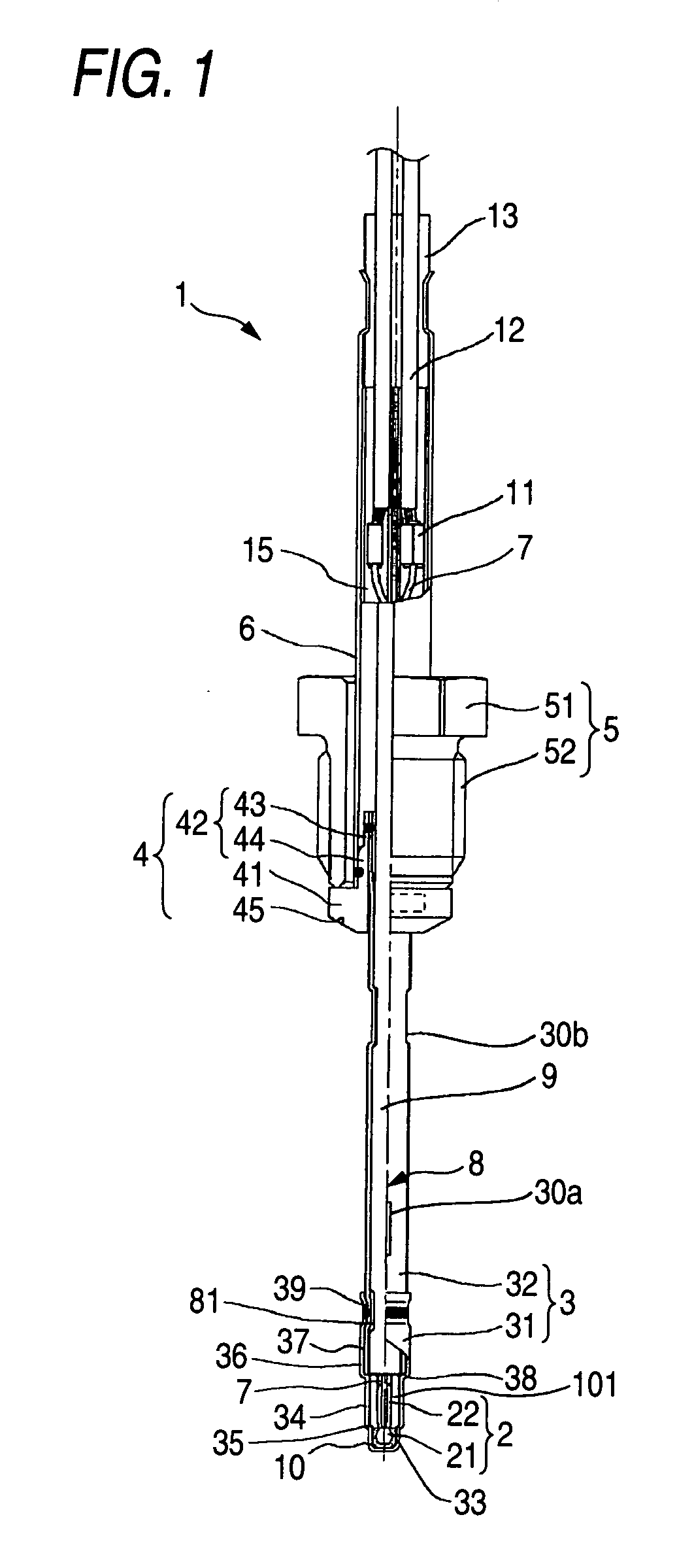
[0065]A temperature sensor 1 which is a first embodiment of the present invention will be described with reference to the drawings. FIG. 1 is a partly cutaway sectional view showing the structure of the temperature sensor 1 according to this embodiment. FIG. 2 is an enlarged view of the neighborhood of a thermistor element 2 which is an important part of the temperature sensor 1 depicted in FIG. 1. The temperature sensor 1 uses the thermistor element 2 as a thermal sensing element. In the condition that the temperature sensor 1 is mounted in an exhaust pipe of a car so that the thermistor element 2 is disposed in the exhaust pipe in which exhaust gas flows, the temperature sensor 1 is used for detecting the temperature of the exhaust gas.

[0066]A metal tube 3 is shaped like a bottomed pipe having a front end side (lower side in FIG. 1) blocked. The thermistor element 2 is held in the inside of the front end side of the metal tube 3. The metal tube 3 has a first cylindri...

embodiment 2

(Embodiment 2)

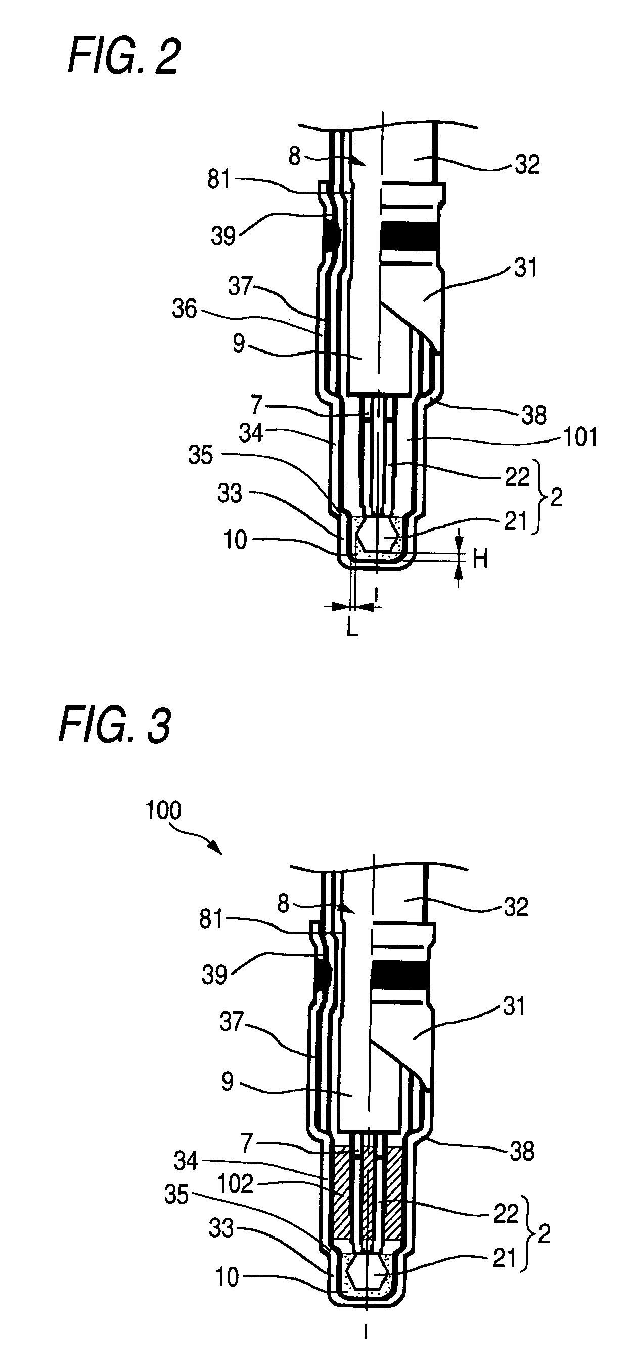
[0096]Next, a temperature sensor according to a second embodiment of the invention will be described with reference to FIG. 3. In the temperature sensor 1 according to Embodiment 1, the void 101 is formed between the rear end surface of the cement 10 and the front end surface of the sheath pipe 9. On the contrary, the temperature sensor 100 according to Embodiment 2 is different from the temperature sensor 1 according to Embodiment 1 in that an adiabatic member is provided between the rear end surface of the cement and the front end surface of the sheath pipe. Embodiment 2 is the same as Embodiment 1 in the other points. Accordingly, only the different point will be described and the description of the same points will be omitted.

[0097]FIG. 3 is an enlarged view of the neighborhood of a thermistor element 2 which is an important part of the temperature sensor 100. In the temperature sensor 100, an adiabatic member 102 made of alumina ceramic fiber is provided between t...


PUM

PropertyMeasurementUnit
distanceaaaaaaaaaa
diameteraaaaaaaaaa
densityaaaaaaaaaa

Abstract

A temperature sensor (1) including a cylindrical metal tube (3) having a front end side blocked, a thermistor element (2), and a sheath member (8) connected to the thermistor element (2) and held in the inside of the metal tube (3), wherein: the metal tube (3) has a small-diameter portion (33) located on the front end side and entirely having an inner diameter smaller than the outer diameter of the sheath member (8), and a large-diameter portion (36) located on the rear end side of the small-diameter portion (33) and having a diameter larger than the outer diameter of the small-diameter portion (33); and a thermistor sintered body (21) is held in the small-diameter portion (33) and cement (10) is filled in between a front end of the thermistor sintered body (21) and a front end of an inner wall of the metal tube (3) and on the front end side viewed from a rear end surface of the thermistor sintered body (21).

Description

TECHNICAL FIELD[0001]The present invention relates to a temperature sensor in which a thermal sensing element having a thermal sensing portion such as a thermistor sintered body of semiconductor such as metal oxide, etc. or a metal resistor is held in the inside of a metal tube shaped like a bottomed pipe. More particularly, it relates to a temperature sensor in which a thermal sensing element is disposed in a flow path of a measurement fluid (e.g. exhaust gas) such as the inside of a catalytic converter of an exhaust scrubber of a car or the inside of an exhaust pipe so that the temperature of the measurement fluid can be detected by the thermal sensing element.BACKGROUND ART[0002]There has been heretofore known a so-called exhaust gas temperature sensor using a thermistor element as a thermal sensing element for detecting the temperature of exhaust gas flowing in an exhaust gas flow path such as the inside of a catalytic converter of an exhaust scrubber of a car or the inside of a...

Claims


Application Information

Patent Timeline
Patent Type & Authority Patents(United States)
IPC IPC(8): G01K13/00G01K1/00G01K7/22G01K1/08G01K1/18H01C1/028H01C1/08
CPCG01K1/18H01C1/08H01C1/028G01K1/08G01K1/22
Inventor HANZAWA, GONISHI, MASAHIKOIWAYA, MASAKICHOSOKABE, TAKAAKI
Owner NGK SPARK PLUG CO LTD
Why Eureka
Try Eureka