Appliance for positioning orthodontic components

a technology for orthodontic components and components, applied in the field of orthodontic components and applications, can solve the problems of human error, manual and as such, in orthodontic procedures, and much effort is made to ensur

Active Publication Date: 2006-09-12
ALIGN TECH
View PDF14 Cites 29 Cited by
  • Summary
  • Abstract
  • Description
  • Claims
  • Application Information

AI Technical Summary

Benefits of technology

[0031]A significant advantage of a positioning appliance in which a video camera section is telescoped into a protective sleeve section and is removable therefrom is that it is only the sleeve section that makes physical contact with the body of the patient and is contaminated thereby. Hence before reusing the appliance, it is only necessary to detach the camera section and then safely sterilize the sleeve section. Hence an appliance in accordance with the invention can expeditiously be put in condition for repeated use.

Problems solved by technology

Thus, during the process of placing the brackets on the teeth, much effort is made to ensure the accurate positioning of the brackets in accordance with their desired position as determined by the treatment plan.
The difficulty with orthodontic procedures, as commonly practiced nowadays, is that they are manual and as such, subject to human error.
A common difficulty relates to the disengagement of the bracket from the positioning tool, as this process typically causes a slight movement of the bracket on the tooth due to inherent and uncontrolled small human movements.
This difficulty is compounded when the orthodontist must place brackets not only on buccal tooth surfaces but also on lingual surfaces.
With existing methods, it is not easy for an orthodontist to properly position brackets on lingual surfaces.
However, the appliance has practical limitations that may interfere with its effective use.
But this is not feasible when the handle, as in the Taub patent appliance, projects beyond its rear end.
Another shortcoming of Taub's positioning appliance is that its video camera which is optically trained on the bracket held ahead of its front end is unshielded and therefore exposed to ambient light.
But the more consequential drawback of the Taub appliance is the difficulties which arise when seeking to repeatedly use the appliance to perform subsequent treatments.
Moreover, the contact portion of the orthodontics appliance must be sterile when put to use.
But when the appliance is used, the portion making contact with the patient becomes contaminated; hence before the appliance can be re-used, it must be again rendered sterile.
One cannot in the case of an appliance of the Taub type simply put the appliance in a dental autoclave in which it will be subjected to superheated steam under high pressure.
To do so would ruin the costly miniature video camera as well as electronic and other components associated with the camera.

Method used


Image

  • Appliance for positioning orthodontic components
  • Appliance for positioning orthodontic components
  • Appliance for positioning orthodontic components

Examples


Embodiment Construction

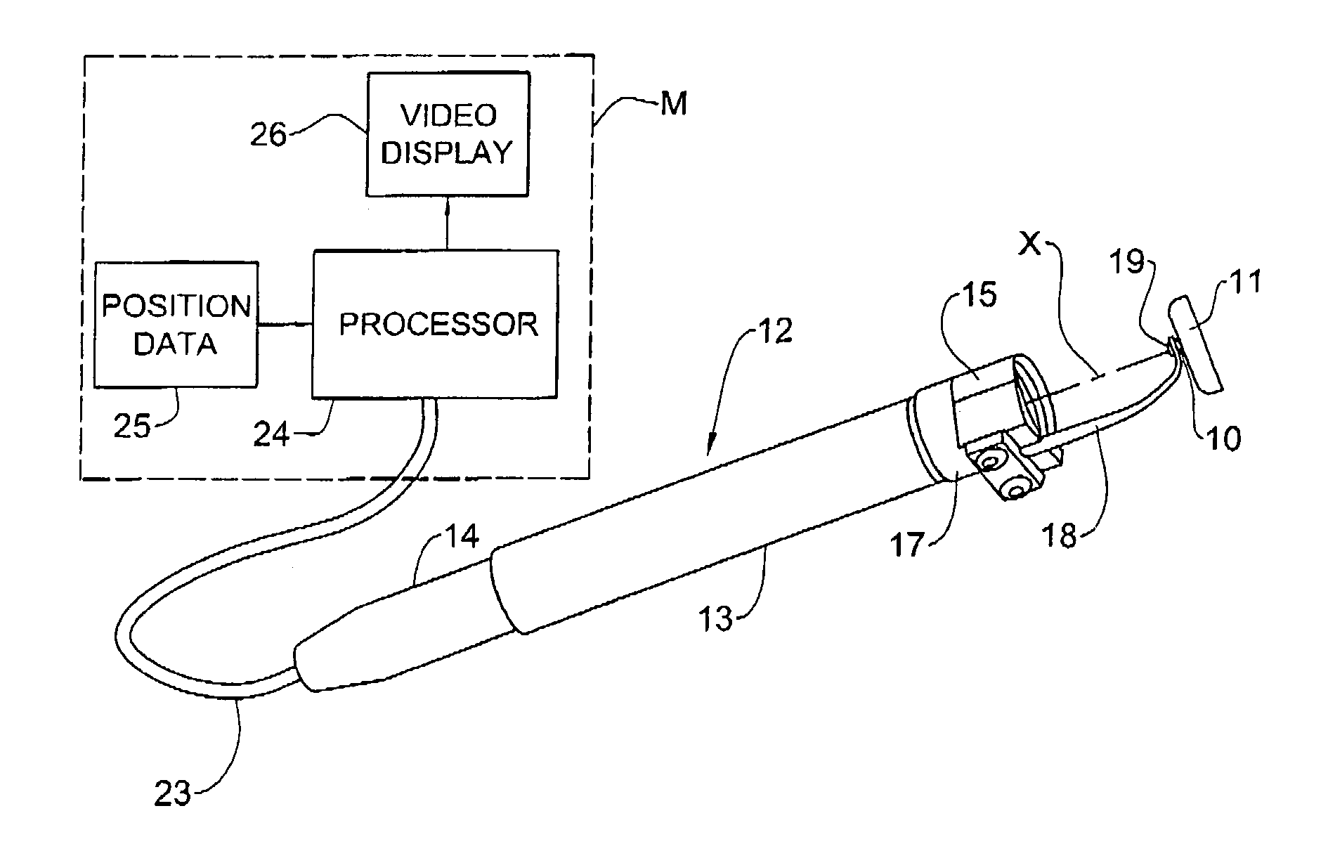
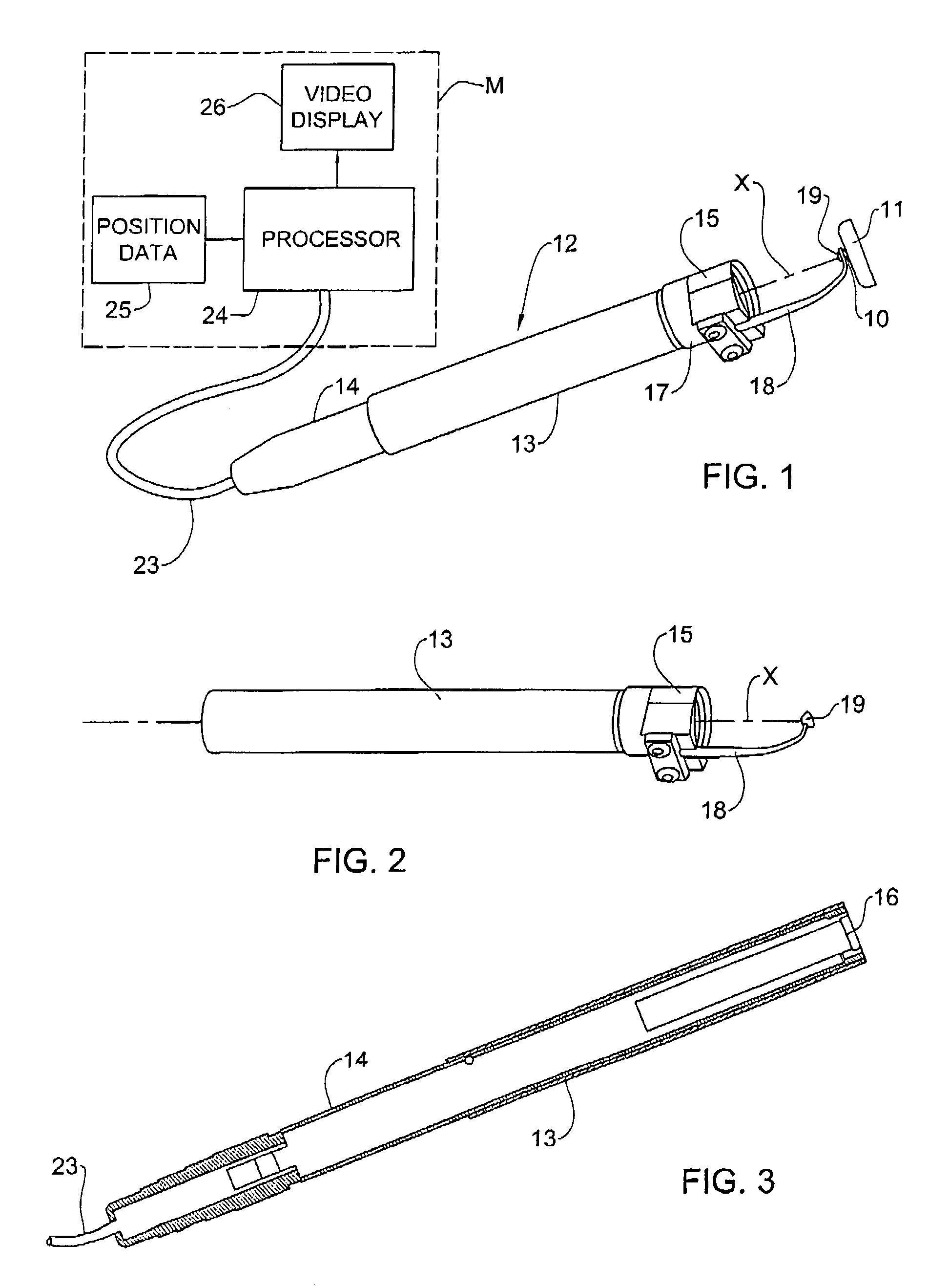
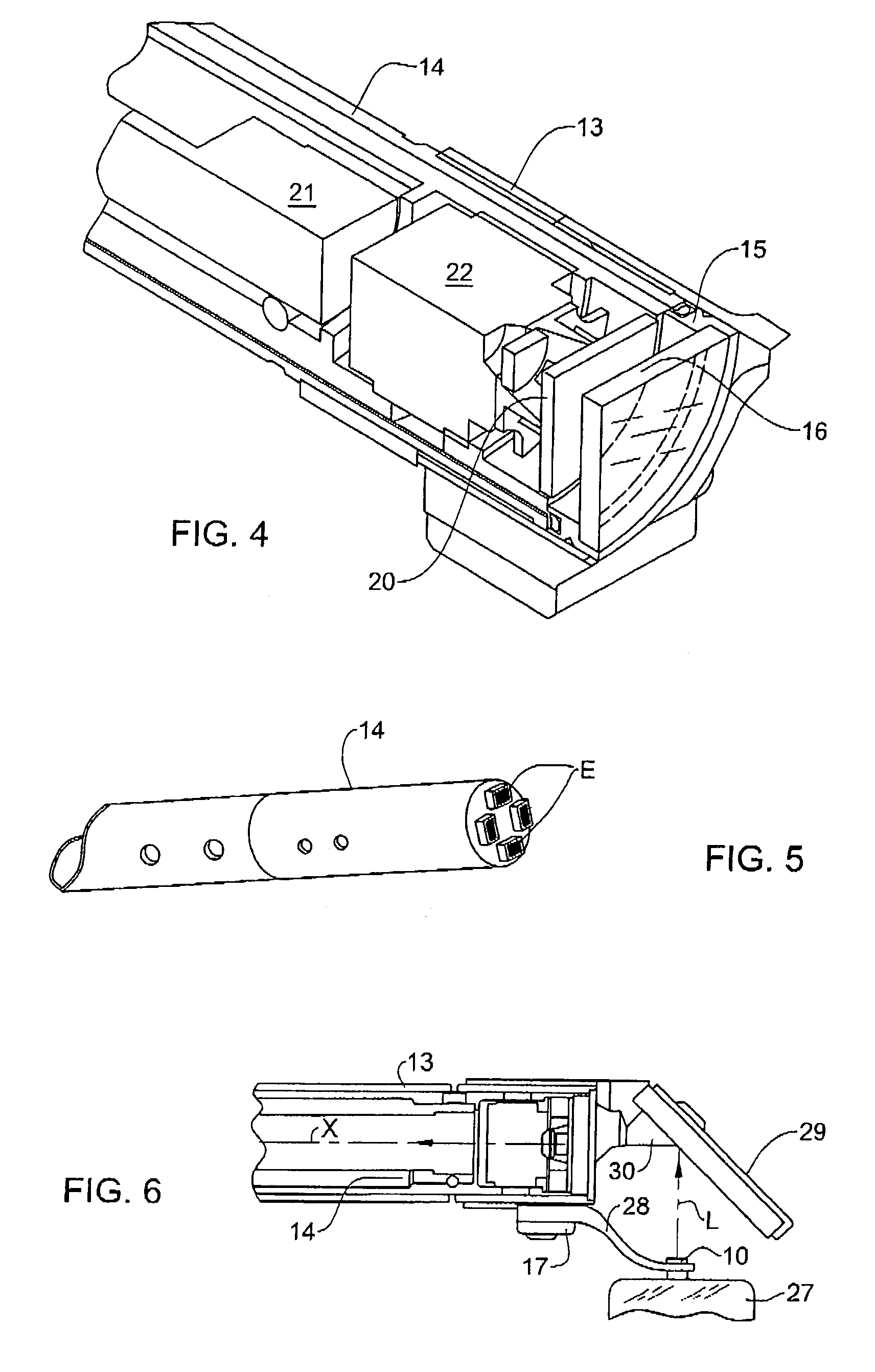
[0057]Direct-View Appliance: Shown in FIGS. 1 to 5 is a direct view appliance 12 for positioning an orthodontic bracket 10 or other component on the front face of a tooth 11 so that it occupies a desired site on the surface appropriate to the orthodontics procedure to which a patient is being subjected.

[0058]Appliance 12 serves to hold bracket 10 against the tooth surface and to shift its position thereon to a desired site at which it is then affixed to the tooth surface. It is important therefore that the bracket be exactly placed at the desired site before it is bonded to the tooth surface, for once the bracket is affixed, it cannot be shifted to correct its position.

[0059]Hence the bonding agent must be such as to allow shifting of the bracket until it occupies the desired site. Preferred agents for this purpose are chemical adhesives and light sensitive adhesives which are activated only when exposed to high intensity light or an ultraviolet beam. The bonding agent is normally i...


PUM


Abstract

A positioning appliance adapted to facilitate an orthodontics procedure in which a bracket or other orthodontic component is placed at a desired site on the surface of a tooth and affixed thereto. The appliance comprises a hand-held tubular wand that has a protective sleeve section and a camera section telescoped in the sleeve section. A window is mounted at the front end of the sleeve section and a finger projecting therefrom is adapted to hold the bracket at a position abutting the tooth surface. A camera is housed in the camera section to capture through the window an image of the bracket on the surface of the tooth. One or more light sources are housed in the camera section, for irradiating the bracket and the tooth surface with light detectable by the camera. Additional one or more light sources are housed in the camera section and are capable of irradiates light at a wavelength that can cure an adhesive used for affixing the bracket or other orthodontic component to the surface of a tooth.

Description

CROSS REFERENCE TO RELATED APPLICATIONS[0001]This application claims benefit of U.S. Provisional Application 60 / 377,308 filed on May 2, 2002 and U.S. Provisional Application 60 / 416,656 filed on Oct. 7, 2002.FIELD OF THE INVENTION[0002]This invention relates generally to methods for placing a bracket or other orthodontic component on the surface of a tooth of a patient undergoing orthodontic treatment, and to systems and devices for carrying out these methods.STATUS OF PRIOR ART[0003]Orthodontics is the branch of dentistry dealing with teeth irregularities and their connections, such as by means of braces. The primary purpose of orthodontic treatment is to alter the position and reorient an individual's teeth so as to modify or improve their function. Teeth may also be reoriented mainly for cosmetic reasons.[0004]In orthodontic treatment, as currently practiced, it is necessary to affix various orthodontic components to the surfaces of a patient's teeth. (In this specification, we sh...

Claims


Application Information

Patent Timeline
Patent Type & Authority Patents(United States)
IPC IPC(8): A61C7/14A61B1/05A61B1/24A61C7/00A61C13/15
CPCA61B1/0607A61B1/0676A61B1/0684A61C7/146A61C19/004A61B1/24A61B1/05A61B1/0615A61C7/002
Inventor TAUB, ELDADKOPELMAN, AVISHAPIRA, ISRAEL
Owner ALIGN TECH
Why Eureka
Try Eureka