
Stent delivery and retention apparatus

Active Publication Date: 2006-09-12
MEDTRONIC VASCULAR INC
View PDF5 Cites 11 Cited by
  • Summary
  • Abstract
  • Description
  • Claims
  • Application Information

AI Technical Summary

Problems solved by technology

Unfortunately, the limited amount of securment between the stent and the balloon is not always adequate to insure that the stent will properly stay in place while advancing the stent to and through a target lesion.
Additionally, the outer surface of the delivery device is uneven because the stent generally extends outwardly beyond the balloon.
Furthermore, during a coronary intervention, the physician may have difficulty crossing the target lesion.
Such procedures can be risky because the stent may become caught on the edge of the guide catheter.
Sometimes, however, predilatation is not performed, and doctors proceed directly to a primary stenting procedure.
In such cases, there are occasions when the balloon / stent catheter cannot be properly positioned within the target area due to the constriction of the vessel and must be retracted back into the guide catheter.
Even when predilatation is performed, vascular spasms and / or a reclosure of the vessel may occur rendering it difficult to properly align the balloon / stent likewise requiring retraction into the guide catheter.
It is during the retraction process that the stent can catch or impact the edge of the guide catheter causing it to be dislocated or otherwise damaged.
Unfortunately, the balloon material is generally very pliable, and it has been found that when using such devices, the pillows may collapse under the pressure of insertion and / or retraction thus exposing the edge of the stent to the potential impact on the edge of the guide catheter.

Method used


Image

  • Stent delivery and retention apparatus
  • Stent delivery and retention apparatus
  • Stent delivery and retention apparatus

Examples


Embodiment Construction

[0018]The following description is exemplary in nature and is not intended to limit the scope, applicability, or configuration of the invention in any way. Rather, the following description provides a convenient illustration for implementing an exemplary embodiment of the invention. Various changes to the described embodiments may be made in the function and arrangement of the elements described herein without departing from the scope of the invention.

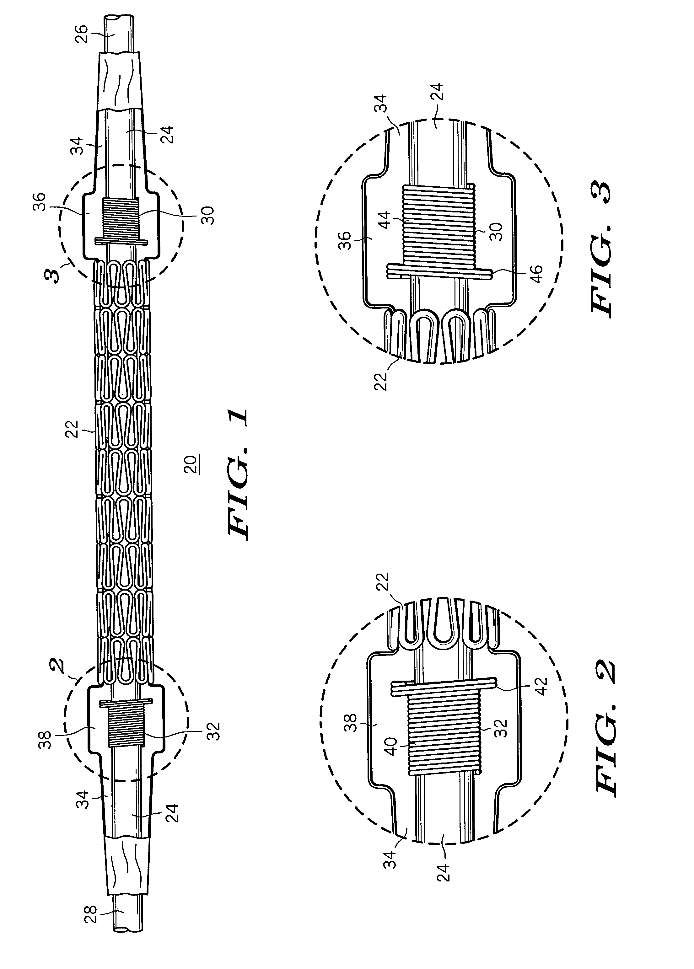
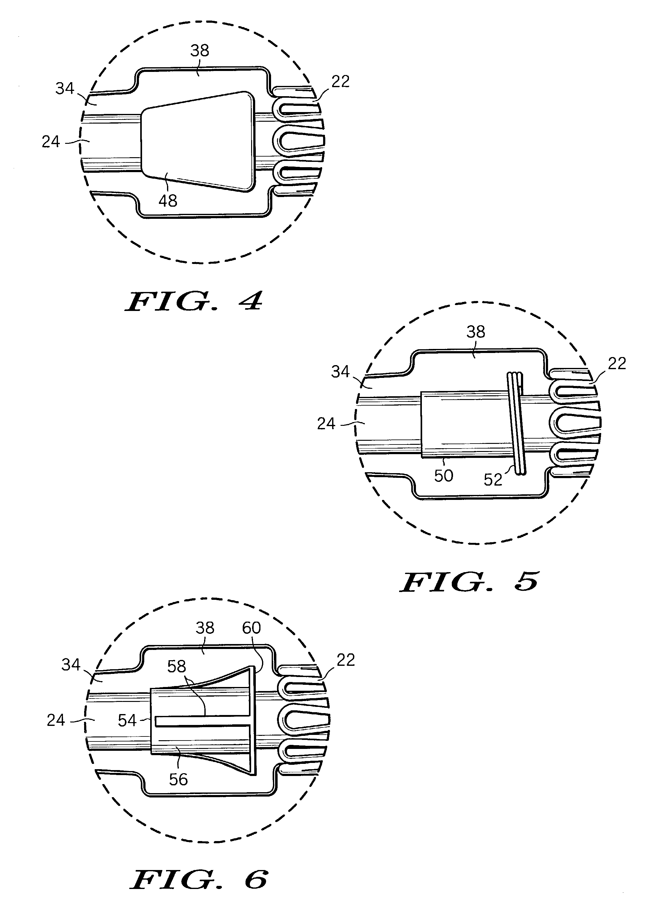
[0019]FIG. 1 is a longitudinal, cross-sectional view of a balloon / stent assembly embodying the principles of the present invention. The balloon / stent assembly shown generally at 20 comprises a stent 22, an inner member or wire lumen 24 having a distal end 26 and a proximal end 28, and distal and proximal radiopaque marker bands 30 and 32 respectively which are positioned on inner member or wire lumen 24 substantially adjacent to distal and proximal ends of stent 22. Stent 22 may be of any form or configuration suitable for the intended...


PUM


Abstract

A stent delivery system comprises an inner member and an expandable balloon mounted in a collapsed state on the inner member, the expandable balloon having a first and a second end. A compressible stent having a first diameter is mounted in a compressed state around the expandable balloon between the first and second ends of the balloon. At least a first retainer pillow is formed in the expandable balloon at its first end and has an outer diameter which is at least substantially equal to the diameter of the compressed stent. A first pillow support member is mounted on the inner member and supports the first retainer pillow to maintain the pillow's outer diameter.

Description

FIELD OF THE INVENTION[0001]This invention relates generally to an intravascular stent deployment apparatus, and more particularly to a stent delivery apparatus including marker bands which support distal and proximal pillows to provide mechanical stent retention.BACKGROUND OF THE INVENTION[0002]In a typical percutaneous transluminal coronary angioplasty (PTCA) procedure, a guiding catheter is percutaneously introduced into the cardiovascular system of a patient. The guide catheter is advanced through a vessel until the distal end thereof is at desired location in the vasculature. A guide wire and a dilatation catheter having a balloon on the distal end thereof are introduced into the guiding catheter with the guidewire sliding through the dilatation catheter. The guide wire is first advanced out of the guiding catheter into the patient's coronary vasculature, and the dilatation catheter is advanced over the previously advanced guide wire until the dilatation balloon is properly pos...

Claims


Application Information

Patent Timeline
IPC IPC(8): A61F11/00A61F2/06A61F2/84
CPCA61F2/958A61F2002/9586
Inventor MURRAY, III, ROBERT J.
Owner MEDTRONIC VASCULAR INC
Learn More