Porous Substrates for Implantation

a porous substrate and implantation technology, applied in the field of porous substrates and porous matrices, can solve the problems of early material failure, implant loosening, bone degeneration, etc., and achieve the effect of enhancing biocompatibility and osseointegration

Inactive Publication Date: 2010-06-03
NATIONAL UNIVERSITY OF IRELAND
View PDF12 Cites 732 Cited by
  • Summary
  • Abstract
  • Description
  • Claims
  • Application Information

AI Technical Summary

Benefits of technology

[0038]Generally speaking, for best integration with bone structures of the body, it is desirable that the substrate has an at least partially open-cell pore structure. More desirably it is the substrate has a fully open-cell pore network. The pore network will desirably extend in the substrate to at least a point of attachment for the substrate to the body part (usually running to at least one surface of the substrate for example a surface which will be arranged in use to be proximate the desired body part). In other words, the pore network will extend from an attachment point on (a surface of) the substrate through the body of the substrate. Closed-cell pore (non-interconnected pore) structures are generally suitable where bio-integration is not required.
[0039]Bio-compatible materials such as mesenchymal cells, osteoprogenitor cells which will subsequently differentiate into bone producing osteoblast cells, may be incorporated into the substrates of the present invention. Other materials such as growth factors and bio-glues may be incorporated or added. Growth factors will induce mesenchymal cells and osteoprogenitor cell differentiation into osteoblasts and the like. Material such as collagen or fibrin can be used to provide a sticky surface to which cells may adhere. For example an injectable protein, in any suitable form such as in gel form can be used. For example an osteoconductive carrier such as fibrin may be employed. Fibrin may be generated from fibrinogen and thrombin. Viral vectors may be incorporated into the substrates and may act to deliver genetic material which may encode for biological material such as growth factors or antibodies that will bind to specific cell proteins, thus attracting cells to the...

Problems solved by technology

This may result in bone degeneration and, consequently, implant loosening.
On the other hand, if the material of the implant is not stiff enough to take repeated loadings, early material failure will occur.
Over time this additional stress absorption may lead to material failure.
These moulds suffer from limitations of accuracy in resolution, particularly due to use of rastering techniques that result in cubiform pores (see for example FIG. 2).
Nonetheless, it is not possible to fabricate substrates having scaffold structures with completely open-cell structures therein using this method.
In particular the final locat...

Method used


Image

  • Porous Substrates for Implantation
  • Porous Substrates for Implantation
  • Porous Substrates for Implantation

Examples


example 1

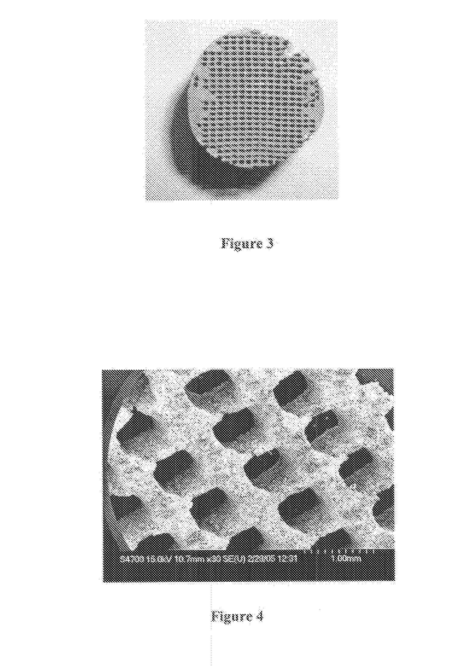
[0181]Porous SS (Stainless Steel) Scaffolds Created Using Thermojet® Support Wax as a Space Holder Material.

[0182]Objective:

[0183]The objective of this experiment was to determine whether certain wax-based materials such as the Thermojet® wax could be used as a space holder material in the production of a porous metal scaffold.

[0184]Materials and Methods:

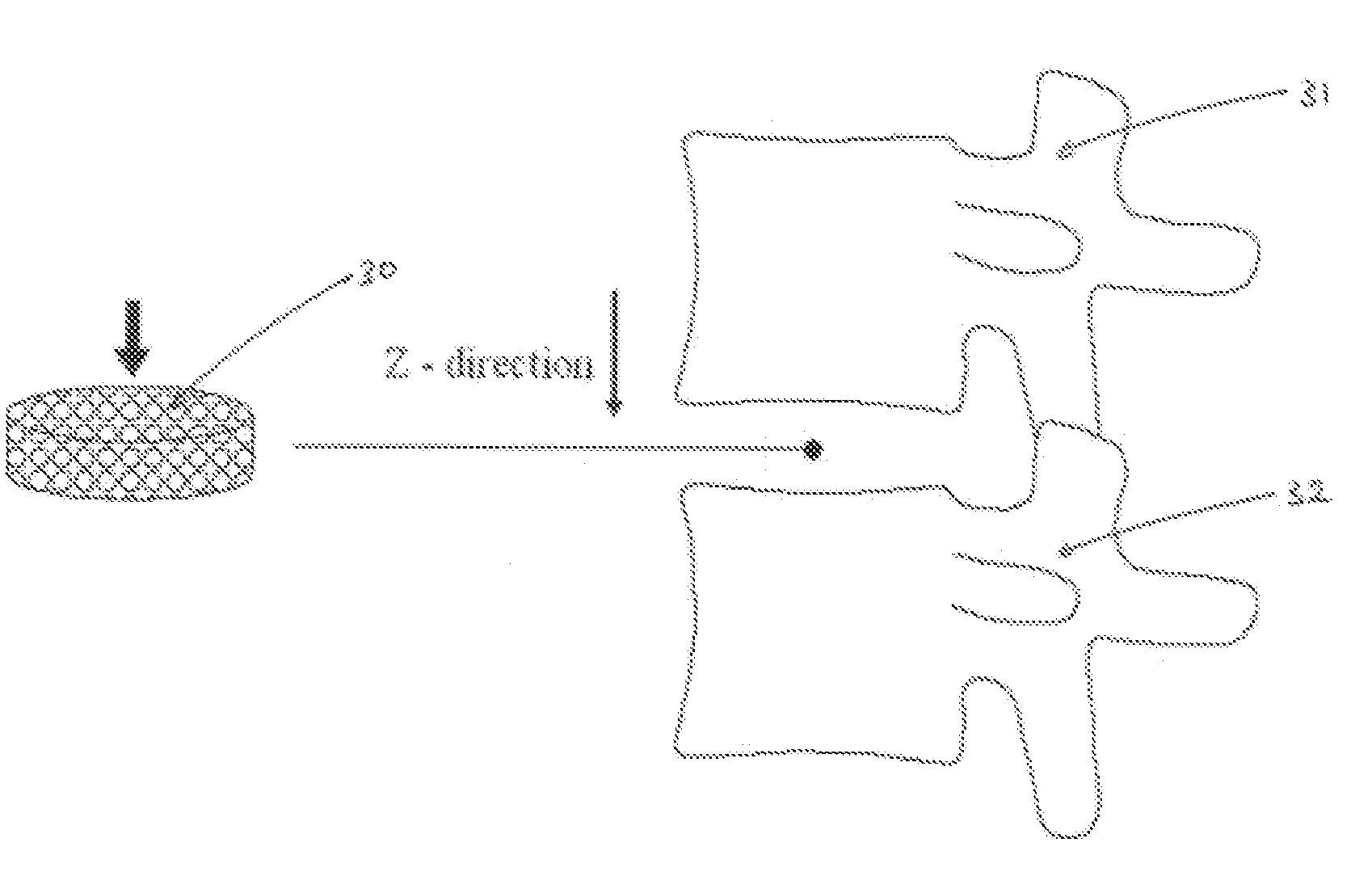
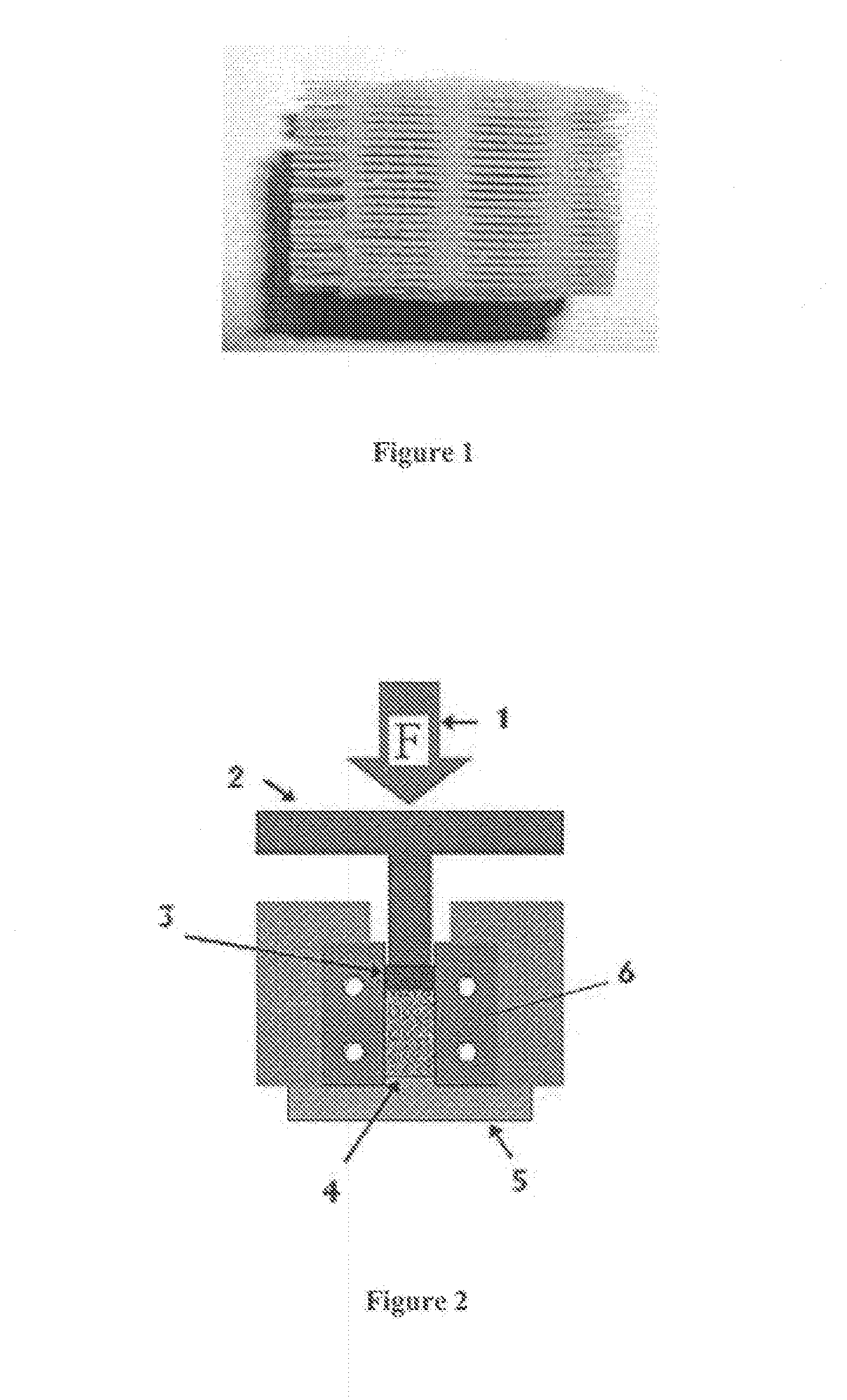
[0185]Samples of Thermojet® wax support material were acquired from printers of 3D-Systems Inc. (Herts, UK, and Valencia, Calif., US). A cylindrical shape was cut from the support material (see FIG. 1) and placed in a custom-made split (compaction) die 6. 316L stainless steel powder (−325 mesh) was dry poured into the die until the porous wax support material was completely immersed. Using a Dennison® hydraulic press 1, the samples were compacted to 300 MPa (see FIG. 2 for a schematic representation of the arrangement). After the “green” compact (green is used to refer to a compacted but not yet sintered material) was removed from t...

example 2

[0187]Creation of Porous SS Scaffold Using Thermojet® Wax Models Made to a Specific Desired Porosity.

[0188]Objective:

[0189]The objective of this experiment was to create a porous SS scaffold that would have predetermined pore characteristics. This can be achieved by first designing a porous scaffold in a piece of software (in this case AutoCAD®) so that the scaffold (including its pores) is completely pre-modelled as to size, shape and location.

[0190]The scaffold model can then be transferred for 3D-printing (3DP), for example to a Thermojet® printer, of the scaffold, utilising in this case a wax material. A similar procedure as described in Example 1 can then be used to create the SS scaffold with the inverse morphology of the porous wax model.

[0191]For the reasons discussed above the models constructed for the present Example utilised struts which zig zag at (alternate) angles of 7° from the perpendicular as shown in FIG. 6. Indeed FIG. 6 shows several of the parameters utilised i...

example 3

Introduction of Heating Element to Compaction Process

[0203]Objective:

[0204]The objective of this experiment was to eliminate the presence of cracks in the compacted wax / SS powder pellet following compaction.

[0205]Materials and Methods:

[0206]The wax was prepared according to the method described in Example 2, but alterations were made to the compaction rig (c.f. FIG. 13), which included a band heater 14 that was placed around the die housing 8 and a thermocouple 15 attached to the housing to monitor its temperature. The rig was positioned in a Dennison® hydraulic press ram and compressed to a pressure of 300 MPa.

[0207]At this stage the hydraulic press 1 was changed from load control to position control to prevent the movement of the upper punch 2. Stopper bolts 7 between the upper punch 2 and the die housing 8 ensured the position of the punch was kept fixed. The band heater 14 was then turned on and a thermocouple 15 used to monitor the rising temperature of the compaction rig. The ...


PUM

PropertyMeasurementUnit
Melting pointaaaaaaaaaa
Mechanical strengthaaaaaaaaaa

Abstract

A porous substrate or implant for implantation into a human or animal body constructed from a structural material and having one or more regions which when implanted are subjected to a relatively lower mechanical loading. The region(s) are constructed with lesser mechanical strength by having a lesser amount of structural material in said region(s) relative to other regions. This is achieved by controlling pore volume fraction in the regions. A spacer is adapted to define an open-cell pore network by taking a model of the required porous structure, and creating the spacer to represent the required porous structure using three-dimensional modelling. Material to form the substrate about the spacer in infiltrated the scaffold structure formed.

Description

FIELD OF THE INVENTION[0001]The present invention relates to porous matrices and to porous substrates. In particular, the present invention relates to porous matrices which are suitable for use as implants, such as implants to be connected to bone for example spinal implants and dental implants. Of particular interest are porous matrices having controlled morphology. Typically the porous matrices of interest are those constructed of biocompatible materials including metallic materials, ceramic materials and polymer materials and combinations thereof. Examples of polymeric materials include polylacetate and polyvinyl alcohol (PVA).[0002]End uses for the porous matrices of the present invention include all applications where mechanical stability is to be imparted to a part of the body, for example where replacement or re-enforcement is required. It is important that such implants are biocompatible in the sense that they do not cause an immediate autoimmune reaction so that the body in...

Claims


Application Information

Patent Timeline
IPC IPC(8): A61F2/44A61F2/28A61B17/56A61B17/70A61B17/86B29C35/02B28B1/48
CPCA61B17/70A61L27/56A61B17/866A61C8/0012A61F2/28A61F2/30724A61F2/30767A61F2/3094A61F2/367A61F2/3676A61F2/4425A61F2/4455A61F2/468A61F2002/2817A61F2002/30004A61F2002/30011A61F2002/30065A61F2002/30131A61F2002/30224A61F2002/30616A61F2002/30909A61F2002/3092A61F2002/30952A61F2002/30958A61F2002/30968A61F2002/30985A61F2210/0071A61F2230/0013A61F2230/0069A61F2250/0014A61F2250/0023A61F2310/00011A61F2310/00017A61F2310/00023A61F2310/00365A61F2310/00377A61F2310/00796A61F2310/00976A61F2310/00982A61F2310/00988A61B17/80A61F2002/30957
Inventor APATSIDIS, DIMITRIOSRYAN, GARRETTPANDIT, ABHAY
Owner NATIONAL UNIVERSITY OF IRELAND
Why Eureka
Try Eureka