Printing plate, circuit board and method of printing circuit board

a technology of circuit boards and printing circuit boards, which is applied in the direction of printed element electric connection formation, photomechanical equipment, instruments, etc., can solve the problems of adversely affecting the quality of the product, the prior art filling technique, etc., and achieve high viscosity and high paste filling quality

Inactive Publication Date: 2006-09-12
PANASONIC CORP
View PDF14 Cites 4 Cited by
  • Summary
  • Abstract
  • Description
  • Claims
  • Application Information

AI Technical Summary

Benefits of technology

[0026]As a result, the cleaning section can remove the paste of high viscosity built up on the edge of the squeegee before the through hole is filled with the paste, and avoid the hard paste from being left on the through hole of the product. This structure thus has

Problems solved by technology

However, the above paste-filling technique of the prior art has a problem peculiar to it as shown in FIG. 17.
It thus gives rise to a problem that

Method used


Image

  • Printing plate, circuit board and method of printing circuit board
  • Printing plate, circuit board and method of printing circuit board
  • Printing plate, circuit board and method of printing circuit board

Examples


first exemplary embodiment

[0045]Description is now provided of a method of filling paste and a plate used for the filling process.

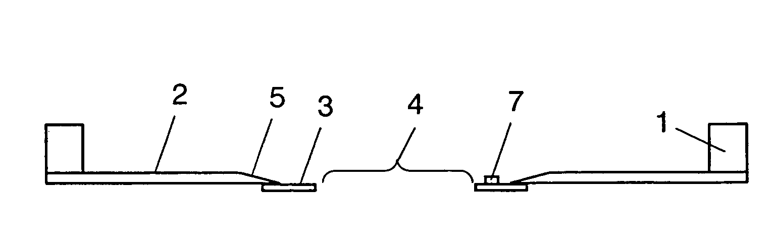
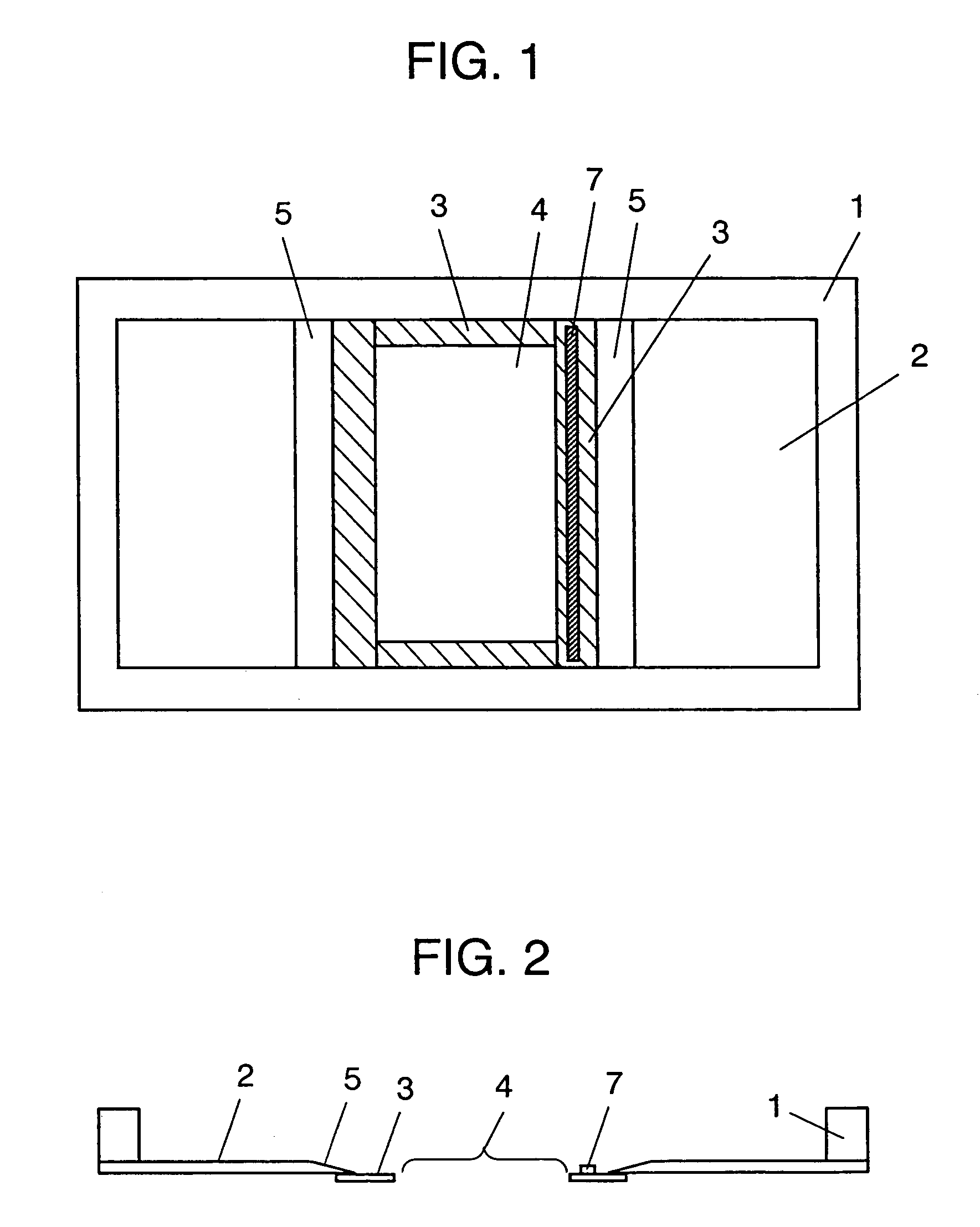
[0046]FIG. 1 is a plan view of a printing plate according to the present invention, and FIG. 2 is a longitudinal sectional view of the printing plate of the present invention.

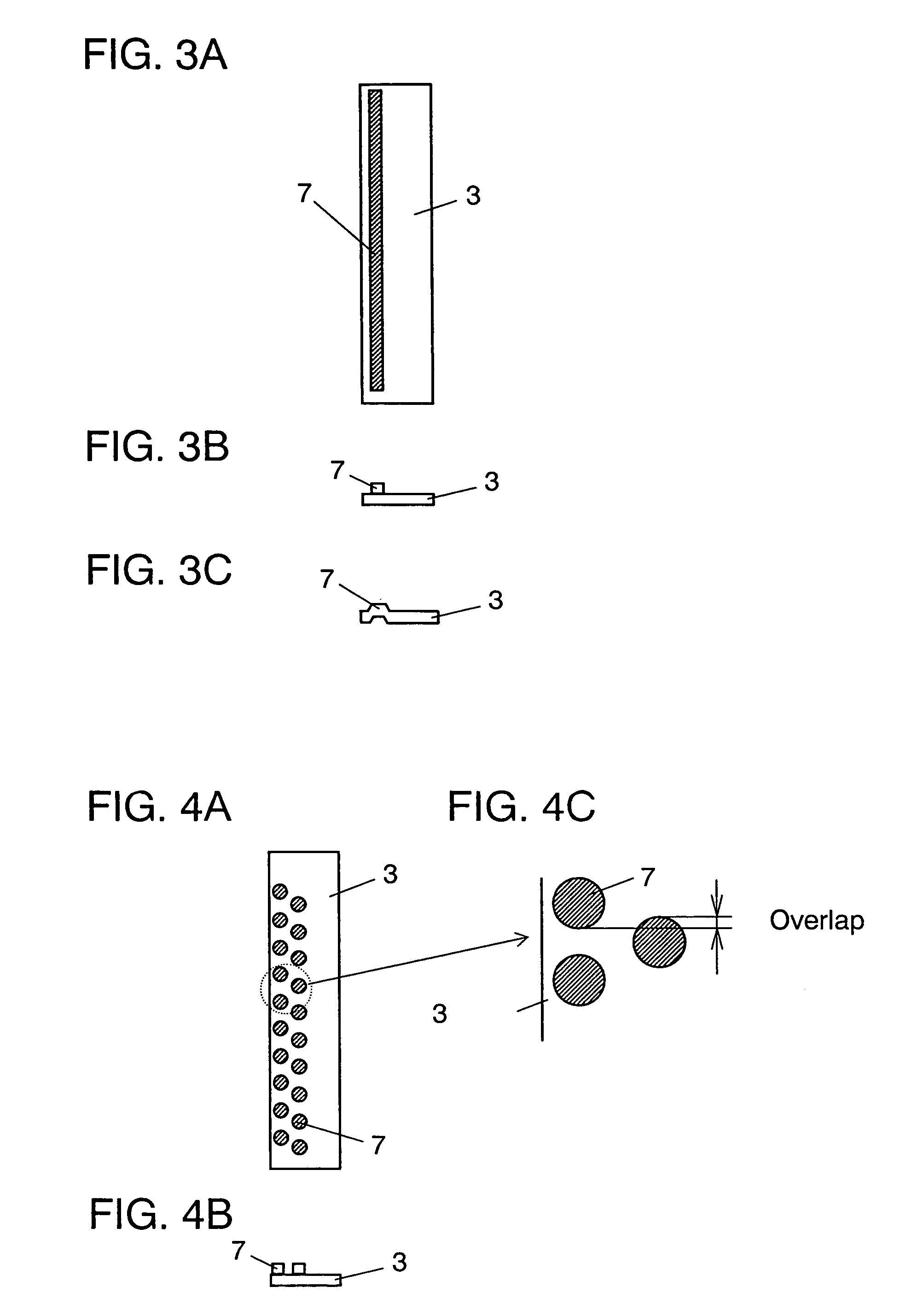
[0047]FIG. 3A through FIG. 3C are illustrations individually showing first metal sheets according to the present, wherein FIG. 3A is a plan view and FIGS. 3B and 3C are cross-sectional views of them.

[0048]FIG. 4A through FIG. 4C are illustrations showing individually different views of a second metal sheet according to the present invention, wherein FIG. 4A is a plan view, FIG. 4B is a cross-sectional view and FIG. 4C is an enlarged plan view of the same.

[0049]FIG. 5 shows cross-sectional views of a printed board, illustrating the production steps for filling it with paste by a squeegeeing method according to the present invention, and FIG. 6 is a cross-sectional view of a part of the printed board which is b...

second exemplary embodiment

[0069]Description is provided hereinafter of a method of manufacturing a printed board according to the present invention.

[0070]FIG. 7 is a plan view of a first printed board according to the present invention, and FIG. 8 is a sectional view of a part of the first printed board according to the present invention.

[0071]FIG. 9 is a plan view of a second printed board according to the present invention, FIG. 10 a sectional view of a part of the second printed board according to the present invention, and FIG. 11 a cross-sectional view of a part of the second printed board which is being filled with paste according to the present invention.

[0072]In FIG. 7 through FIG. 10, prepreg sheet 210 has a size of approximately 300 mm by 500 mm and a thickness of approx. 150 μm. A board material used for prepreg sheet 210 is a composite prepared by having an unwoven fabric formed of all-aromatic polyamide fibers impregnated with a thermosetting epoxy resin. Mask films 220a and 220b are made of suc...


PUM


Abstract

The present invention aims to provide a printing plate capable of preventing paste of high viscosity adhering to an edge of a squeegee from being transferred to and left on a through hole of a printed circuit board when the paste is being filled by a squeegeeing method. The printing plate has a metal sheet (3) provided with a squeegee cleaning section (7) formed thereon and fixed to the back surface of a slanting area (5) of mask (2) attached to a plate framework (1). The through hole of the printed circuit board is filled with paste only after paste of high viscosity adhering to the edge of the squeegee is removed by the squeegee cleaning section (7), to prevent the paste from being left on the through hole, and thereby achieving the printed circuit board of excellent quality.

Description

TECHNICAL FIELD[0001]The present invention relates to a printing plate used for patterning and filling through holes in a two-sided, multilayered or the like printed board with a paste. The invention also relates to a printed board used for a variety of electronic devises, and a printing method for the printed board using the printing plate.BACKGROUND ART[0002]With the advancement of electronic devices in size reduction and high-density packaging, there has been a strong demand in recent years for multi-layering of printed circuit boards not only in the field of industrial electronics but also in the field of consumer electronics.[0003]For such printed circuit boards, it is indispensable to newly develop methods of joining inner via-holes between multilayered circuit patterns in addition to highly reliable structures. Therefore, certain methods have been proposed for manufacturing printed circuit boards of new structures and high-density packaging in which inner via-holes are joined...

Claims


Application Information

Patent Timeline
IPC IPC(8): G03F7/00G03F7/20B41F15/36B41F35/00B41M1/12B41N1/24H05K3/00H05K3/12H05K3/40
CPCB41F15/36B41F35/003B41M1/12B41N1/24B41N1/248H05K3/1225H05K3/4053H05K2203/0191H05K3/4069H05K2201/09063H05K2201/09709H05K3/0052
Inventor TAKENAKA, TOSHIAKINISHII, TOSHIHIROKOMODA, HIDEAKIKONDO, TOSHIKAZUNAKAMURA, SHINJI
Owner PANASONIC CORP
Why Eureka
Try Eureka