Dielectric barrier discharge lamp with pinch seal

Inactive Publication Date: 2006-09-12
PATENT TREUHAND GESELLSCHAFT FUR ELECTRIC GLUEHLAMPEN MBH
View PDF12 Cites 0 Cited by
  • Summary
  • Abstract
  • Description
  • Claims
  • Application Information

AI Technical Summary

Benefits of technology

[0008]The object of the invention is to avoid the above-mentioned drawbacks and to provide a dielectric barrier discharge lamp with a simplified closure technique.
[0011]Advantages of this solution are the simple and therefore inexpensive production and the fact that the supply conductors are fixedly and integrally connected to the lamp. This makes it possible to dispense with an additional production step for electrically connecting inner electrode and supply conductor, for example by means of soldering, which would otherwise be required. Rather, sufficient and reliable electrical contact between inner electrode and supply conductor is produced by the pinch alone. To make it easier to bring the inner electrode and supply conductor into contact, it is advantageous for a widening of the otherwise thin electrode track to be provided at that end of the inner electrode which is intended for contact, for example by a wide soldering dot being applied to said end.
[0012]Moreover, it is advantageous for the pinch to be designed in such a manner that it completely surrounds the connection between the at least one inner electrode and the associated supply conductor. This effectively protects the connection from external environmental influences, such as oxidation, moisture, etc.
[0014]In a preferred embodiment, the at least one inner electrode is realized as a conductor track arranged on the inner side of the wall of the discharge vessel. The at least one supply conductor is preferably realized by an electrically conductive wire, for example made from an iron-nickel alloy. In this context, it has proven advantageous for the wire diameter to be in the range between 0.3 mm and 1.5 mm, preferably in the range between 0.5 mm and 1.0 mm. With wires of larger diameters, there is an increased risk of leaks, and with wires with a smaller diameter the mechanical robustness decreases and therefore so does the practical viability of such wires.

Problems solved by technology

One drawback is that an additional soldering glass layer, as a gastight joining means, is required between stopper and vessel wall.
A drawback of this arrangement is the relatively high production costs.

Method used


Image

  • Dielectric barrier discharge lamp with pinch seal
  • Dielectric barrier discharge lamp with pinch seal
  • Dielectric barrier discharge lamp with pinch seal

Examples


Embodiment Construction

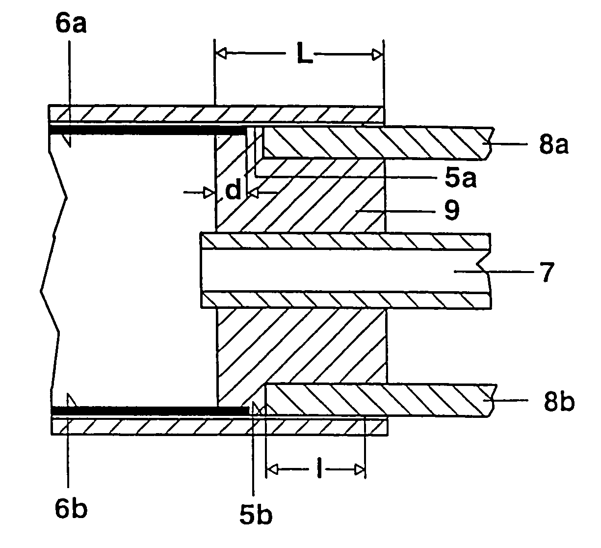
[0024]The production and technical features of the dielectric barrier discharge lamp according to the invention are illustrated in the figures described below.

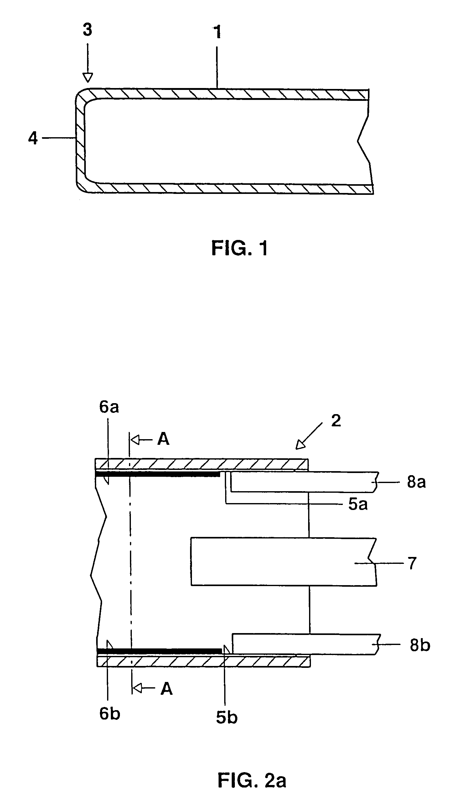
[0025]FIG. 1 shows part of a discharge tube 1 with an external diameter of approx. 10 mm made from soda-lime glass (e.g. glass No. 360 produced by Philips and / or AR-Glass produced by Schott), which is initially still open at a first end 2 but has already been closed at the other end 3 by means of a fused butt joint 4.

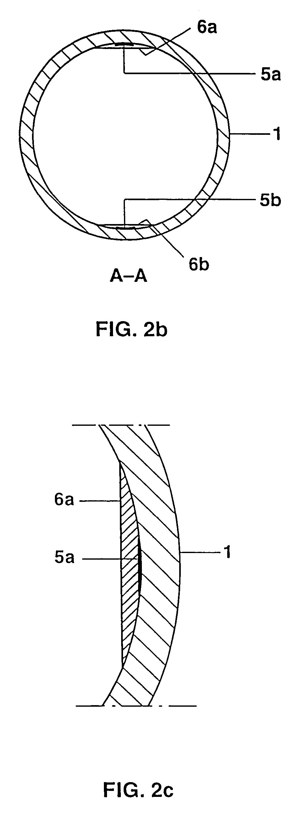
[0026]FIGS. 2a, 2b show the still open end 2 of the discharge tube 1 in the form of a diagrammatic partial longitudinal sectional view and a cross-sectional view on line AA respectively. The inner wall of the discharge vessel 1 has already been provided with two diametrically arranged inner electrodes 5a, 5b which are formed as linear conductor tracks and are made from silver with a thickness of approx. 10 μm and a width of approx. 1 mm, covered with a dielectric barrier 6a, 6b made from soldering glass, thickness...


PUM


Abstract

A dielectric barrier discharge lamp with a discharge vessel (1) has at least one inner electrode (5a; 5b) which is covered with a dielectric layer (6a; 6b) and is arranged on the inner side of the discharge vessel (1) The at least one inner electrode (5a; 5b) is electrically conductively connected to a supply conductor (8a; 8b) in a leadthrough region, the leadthrough region being realized by a gastight pinch (9).

Description

TECHNICAL FIELD[0001]The invention is based on a dielectric barrier discharge lamp having at least one inner electrode, in particular with a tubular discharge vessel.[0002]With this type of lamps, although the electrodes are arranged inside the discharge vessel, at least the electrode of one polarity is separated from the interior of the discharge vessel by a dielectric, for example by a dielectric coating. In operation, this gives rise to what is known as a single-sided dielectric barrier discharge. Alternatively, it is also possible for all the electrodes to be provided with a dielectric barrier. This is then a two-sided dielectric barrier discharge.[0003]Dielectric barrier discharge lamps with inner electrodes have the advantage that the thickness and the materials properties of the dielectric layer can be optimized in terms of the discharge properties and lamp efficiency. The dielectric layer is typically from approximately one hundred to a few hundred μm thick. In the case of o...

Claims


Application Information

Patent Timeline
IPC IPC(8): H01J17/18H01J5/44H01J65/00H01J61/36H01J65/04H01K1/62
CPCH01J65/046H01J5/44H01J61/368
Inventor BSCHORER, GEORG
Owner PATENT TREUHAND GESELLSCHAFT FUR ELECTRIC GLUEHLAMPEN MBH
Why Eureka
Try Eureka