Cancellation of dead time effects for reducing common mode voltages

a common mode voltage and dead time effect technology, applied in control systems, power conversion systems, electrical equipment, etc., can solve the problems of increased installation costs and increased production costs, and achieve the effect of reducing the peak-to-peak common mode voltage and reducing costs

Inactive Publication Date: 2006-09-12
ROCKWELL AUTOMATION TECH
View PDF13 Cites 67 Cited by
  • Summary
  • Abstract
  • Description
  • Claims
  • Application Information

AI Technical Summary

Benefits of technology

[0014]where Td is a dead time that is predetermined for the switches in a power conversion device. Gating signals to switches for the three phases in the power conversion device are then delayed to produce the voltage difference and reduce the dead time effects in facilitating common mode voltages in a motor.

Problems solved by technology

Passive circuits including filters and transformers have been employed to correct this problem, but with increased production costs and increased installation costs.

Method used


Image

  • Cancellation of dead time effects for reducing common mode voltages
  • Cancellation of dead time effects for reducing common mode voltages
  • Cancellation of dead time effects for reducing common mode voltages

Examples


Embodiment Construction

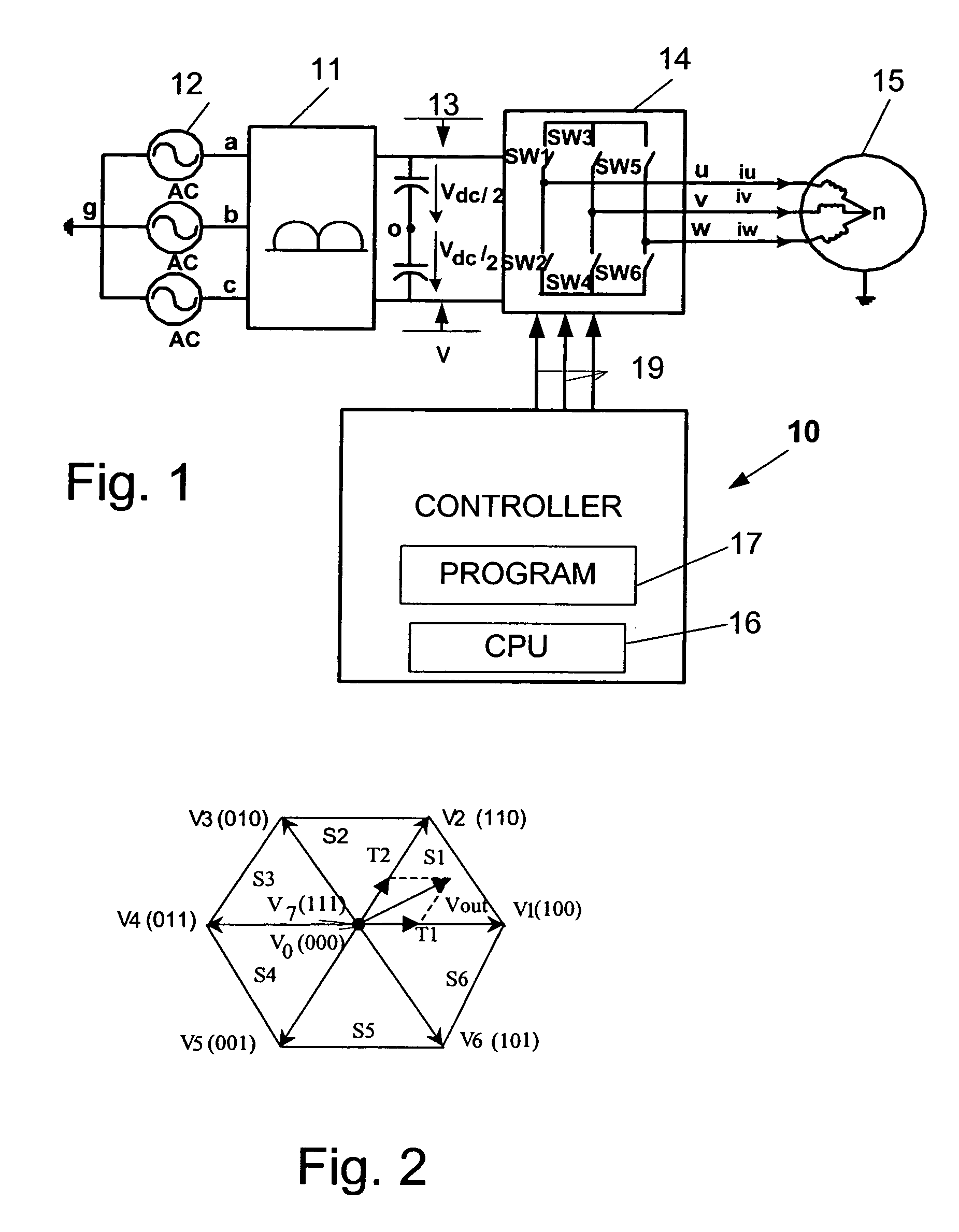
[0034]FIG. 1 illustrates a block diagram of an AC drive controller 10 for controlling an AC-to-DC converter 11 including a boost rectifier for converting three-phase AC source voltages from an AC voltage supply 12 to DC voltages, Vdc, on a DC bus 13. The DC bus 13 interfaces the AC-to-DC converter 11 to a DC-to-AC inverter 14, which is typically a three-phase bridge network of solid state switches SW1–SW6, preferably IGBT's, which are switched at high frequency to generate pulse width modulation (PWM) or other types of modulated low frequency power signals iu, iv, iw, which are supplied to an AC motor 15.

[0035]The controller 10 includes a microelectronic CPU 16 operating according to instructions in a control program 17 stored in memory. The program 17 includes instructions for performing regulation of a DC bus voltage and regulation of current supplied to the motor 15. The controller provides gating signals 19 to control the switching of the switches SW1–SW6 in the inverter 14.

[003...


PUM


Abstract

Methods and apparatus for canceling dead time effects in the form of common mode voltages produced by a three-phase power conversion device in a rectifier / inverter variable frequency drive (VFD) system includes limiting the voltage difference between phase voltages at certain switching transition times to an amount δ, that is a function of the dead time that is specified for the switches and delaying gating signals to the switches to remove unexpected pulses produced by common mode voltages.

Description

CROSS-REFERENCE TO RELATED APPLICATIONS[0001]Not applicableSTATEMENT REGARDING FEDERALLY SPONSORED RESEARCH[0002]Not applicableTECHNICAL FIELD[0003]The field of the invention is control systems for controlling the operation of AC motors.BACKGROUND ART[0004]A well known type of AC drive includes an AC-to-DC converter including a boost rectifier for converting three-phase AC source voltages to DC voltages on a DC bus. The DC bus interfaces the AC-to-DC converter to a DC-to-AC inverter, which is typically a three-phase bridge network of solid state switches, which are switched at high frequency to generate pulse width modulation (PWM) or other types of modulated low frequency power signals which are supplied to an AC motor. These systems generate a common mode voltage measured between a neutral in the motor and an electrical ground. These also generate common mode currents in part the result of parasitic capacitances between mechanical parts in the motor and ground, and between mechani...

Claims


Application Information

Patent Timeline
Patent Type & Authority Patents(United States)
IPC IPC(8): H02M1/12H02M1/00H02M7/5387
CPCH02M7/53873H02P27/08H02M2001/385H02M1/385
Inventor YIN, QIANGKERKMAN, RUSSEL J.LUKASZEWSKI, RICHARD A.
Owner ROCKWELL AUTOMATION TECH
Why Eureka
Try Eureka