
Linear voltage regulator with selectable light and heavy load paths

a linear voltage regulator and load path technology, applied in the direction of electric variable regulation, process and machine control, instruments, etc., can solve the problems of large gate capacitance, poor efficiency of conventional linear voltage regulators in light-load mode, and large current consumption, so as to achieve small current driving capability, and large current driving capability

Inactive Publication Date: 2006-09-12
GLOBAL MIXED MODE TECH
View PDF7 Cites 45 Cited by
  • Summary
  • Abstract
  • Description
  • Claims
  • Application Information

AI Technical Summary

Benefits of technology

"The present invention provides a linear voltage regulator that can achieve optimal efficiency during a light-load mode. It includes two power transistors connected in parallel between an input voltage and an output voltage, with one transistor having a larger current driving capability and the other having a smaller current driving capability. During the light-load mode, the regulator activates only the smaller transistor to reduce current consumption and enhance efficiency. Additionally, the regulator includes a current sensing unit for detecting a current flowing through the smaller transistor, and when the detected current exceeds a predetermined threshold, it is determined to be in a heavy-load mode. In this mode, the regulator activates both transistors to provide a large output current to a load."

Problems solved by technology

Therefore, the conventional linear voltage regulator has a poor efficiency during the light-load mode.
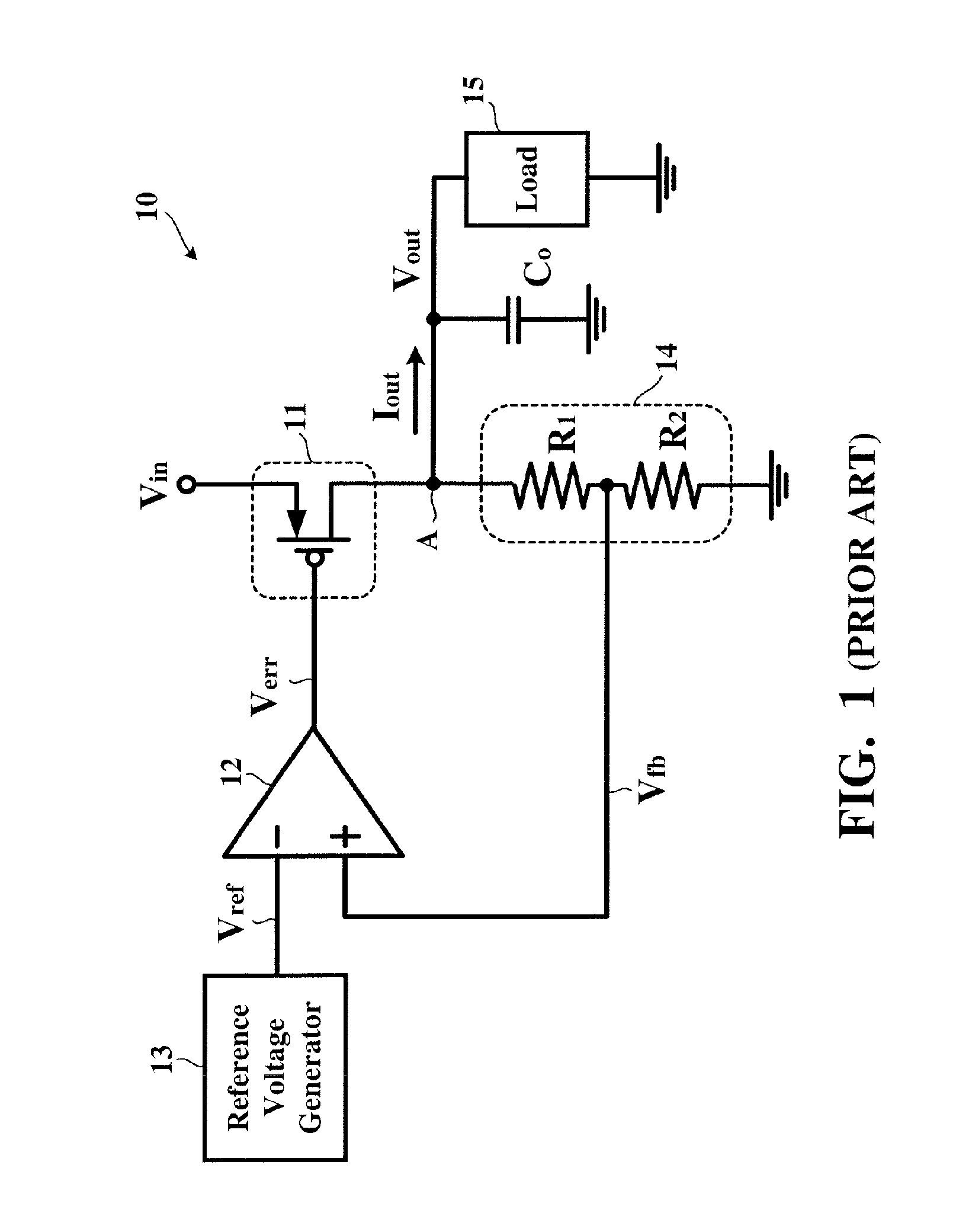
However, the large-dimension power transistor 11 causes a larger gate capacitance.
For more appropriately controlling the gate of the power transistor 11, the error amplifier 12 must be designed to have a smaller output impendence, which results in a larger current consumption.

Method used


Image

  • Linear voltage regulator with selectable light and heavy load paths
  • Linear voltage regulator with selectable light and heavy load paths
  • Linear voltage regulator with selectable light and heavy load paths

Examples


Embodiment Construction

[0016]The preferred embodiments according to the present invention will be described in detail with reference to the drawings.

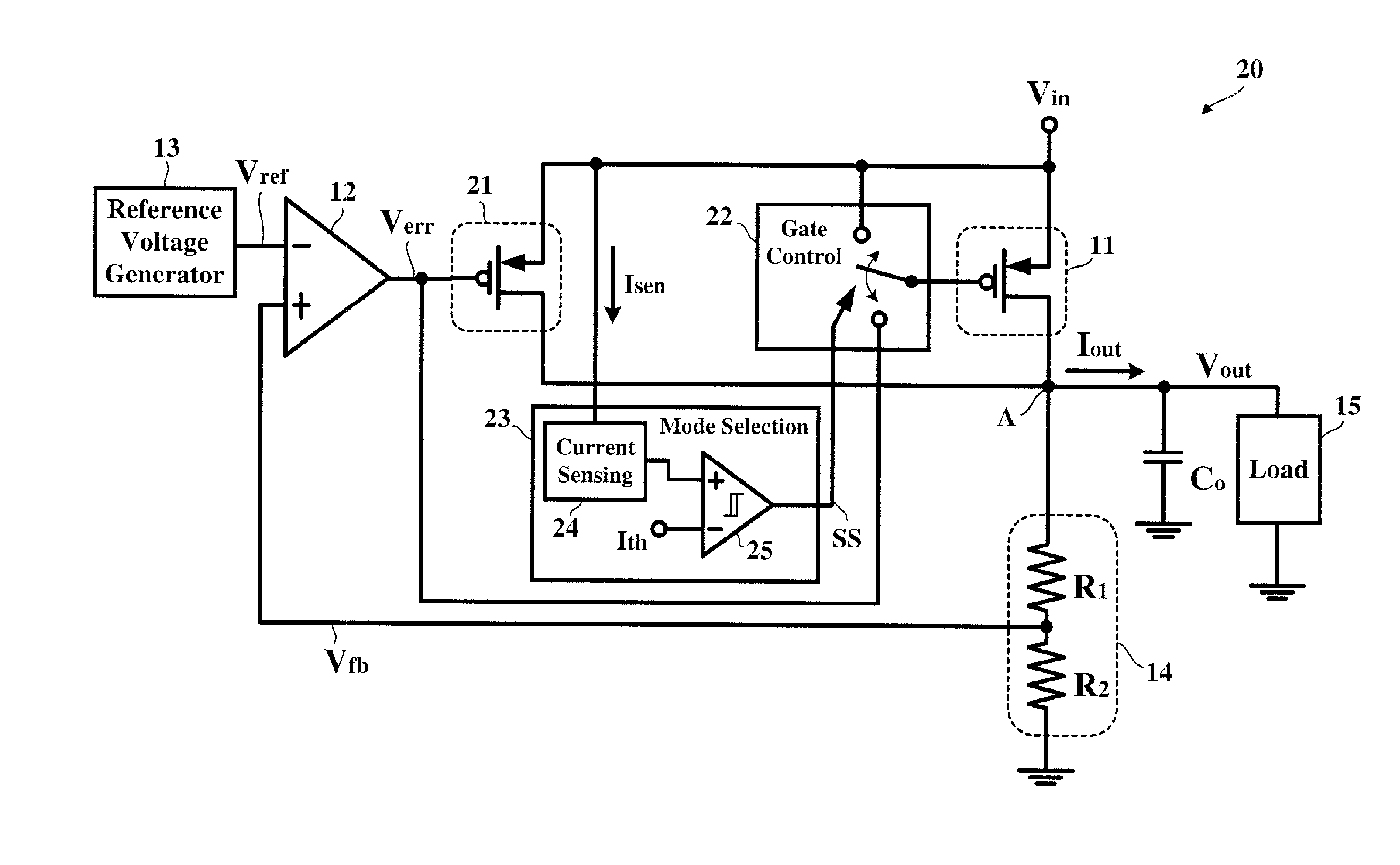
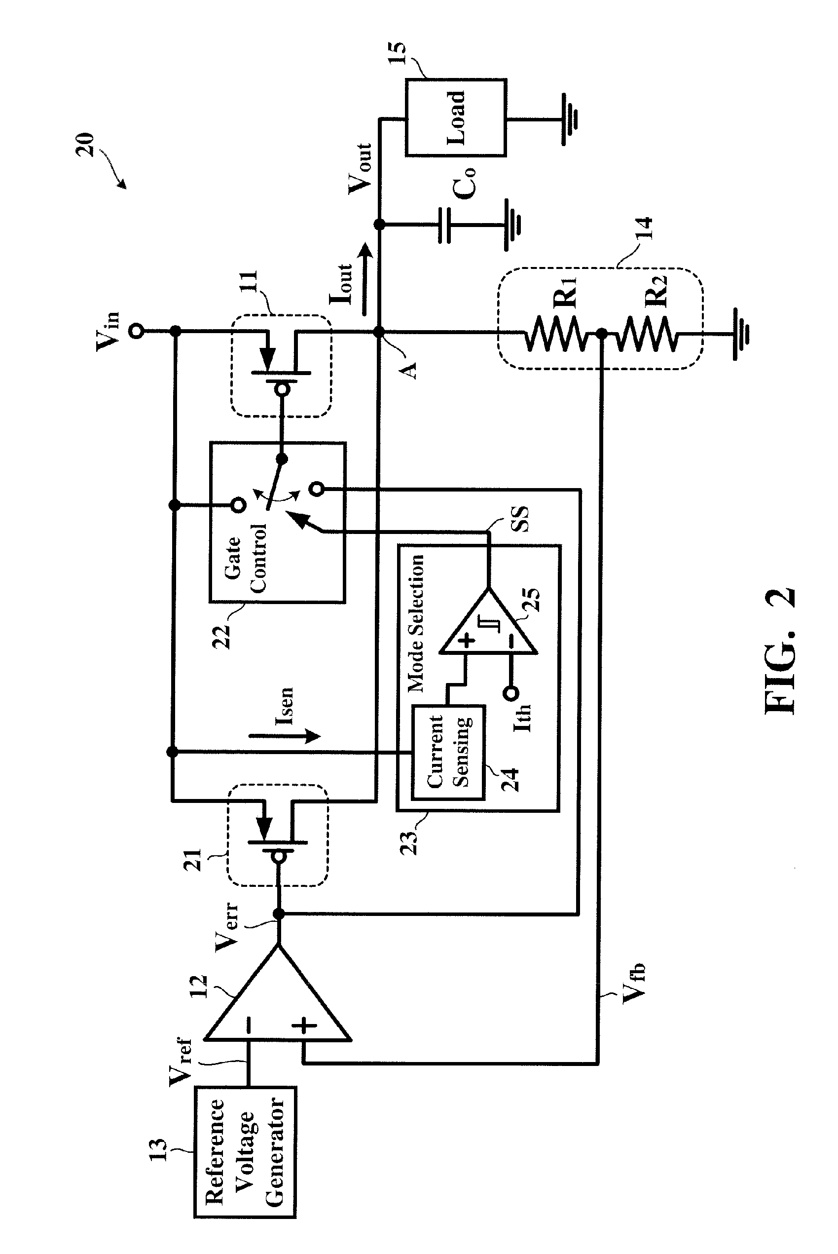
[0017]FIG. 2 is a circuit block diagram showing a linear voltage regulator 20 according to the present invention. In FIG. 2, for simplicity, like reference numerals have been used to identify like components illustrated in FIG. 1 and previously described, with additional detail being shown in the timing and control portion of the circuit relevant to the present invention. The linear voltage regulator 20 according to the present invention has a heavy-load power transistor 11 and a light-load power transistor 21, both connected in parallel between the input voltage Vin and the output terminal A. The dimension of the light-load power transistor 21 is designed to be smaller than that of the heavy-load power transistor 11, resulting in that the current driving capability of the light-load power transistor 21 to be smaller than that of the heavy-load power transist...


PUM


Abstract

A light-load power transistor and a heavy-load power transistor are connected in parallel between an input voltage and an output voltage. The light-load power transistor has a smaller current driving capability, i.e. a smaller dimension of a current path. During a light-load mode, only is the light-load power transistor activated to reduce the current consumption caused by an error amplifier, thereby enhancing the efficiency. When a detection current signal is higher than a threshold current signal, the heavy-load power transistor is additionally activated through a gate control circuit by a mode selection circuit, thereby achieving a sufficient current driving capability.

Description

BACKGROUND OF THE INVENTION[0001]1. Field of the Invention[0002]The present invention relates to a linear voltage regulator and, more particularly, to a linear voltage regulator capable of enhancing the efficiency during a light-load mode.[0003]2. Description of the Related Art[0004]Voltage regulators supply a required output current at a regulated output voltage to a load. Linear voltage regulators employ a power transistor operated in the ohmic region as a passive device. The output voltage is fed back to control a variable resistance of the power transistor for obtaining the regulated output voltage from an input voltage, e.g. a battery voltage, minus a potential difference across the variable resistance. During a light-load mode, the necessary output current is reduced but the current consumption of an error amplifier remains unchanged. Therefore, the conventional linear voltage regulator has a poor efficiency during the light-load mode.[0005]FIG. 1 is a detailed circuit diagram...

Claims


Application Information

Patent Timeline
Patent Type & Authority Patents(United States)
IPC IPC(8): G05F1/40
CPCG05F1/575G05F1/569
Inventor CHEN, TIEN-TZUSU, FANG-TE
Owner GLOBAL MIXED MODE TECH
Learn More