
Method for metal object identification using a three-dimensional steerable magnetic field antenna

Inactive Publication Date: 2006-09-12
THE JOHN HOPKINS UNIV SCHOOL OF MEDICINE
View PDF13 Cites 18 Cited by
  • Summary
  • Abstract
  • Description
  • Claims
  • Application Information

AI Technical Summary

Benefits of technology

[0014]It is another object of the present invention to provide a more efficient method for identifying a buried metal object with a body of revolution (BOR) using a three-dimensional steerable magnetic field (3DSMF) antenna.
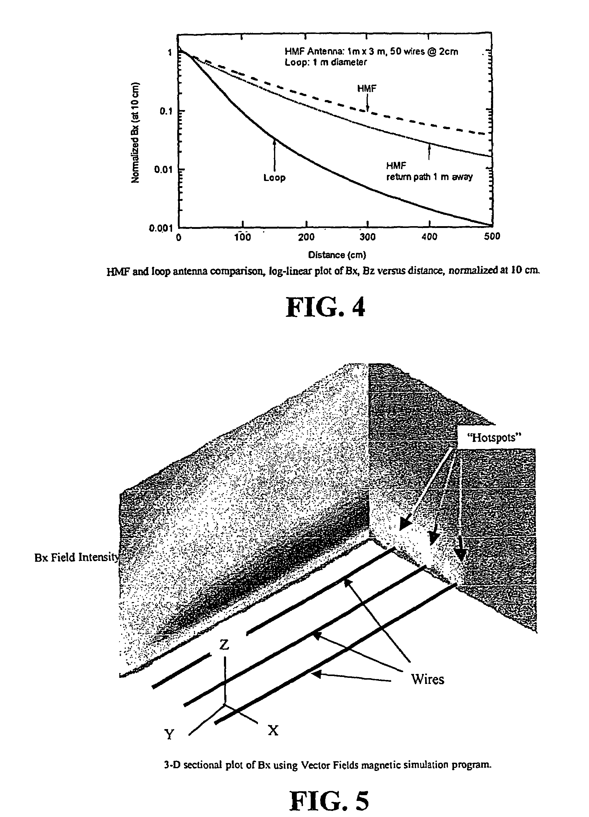
[0017]One of the potential advantages of the steerable 3-D magnetic field sensor system is the relatively uniform magnetic field that is created over a large volume by the HMF antennas. A second potential advantage of the EMI sensor system is that compared to a conventional loop antenna, the magnetic field intensity falls off slowly with distance from the plane of the antenna. These two advantages potentially make the steerable 3-D magnetic field sensor system well suited for detection and classification of metal targets buried deeply in the ground (e.g., landmines, unexploded ordnance (UXO) and underground utilities).

Problems solved by technology

If the magnetic field is in fact complex, the target's time or frequency response to the field is not well characterized.
This may tend to complicate or confound a target identification algorithm.
As noted above, prior art EMI metal detectors that use loop magnetic field antennas do not address all of these issues.

Method used


Image

  • Method for metal object identification using a three-dimensional steerable magnetic field antenna
  • Method for metal object identification using a three-dimensional steerable magnetic field antenna
  • Method for metal object identification using a three-dimensional steerable magnetic field antenna

Examples


Embodiment Construction

[0049]A discussion is first made as to the underlying physics utilized by a horizontal magnetic field (HMF) sensor system of the present invention. Following this discussion, a description is provided of the steerable two-dimensional HMF sensor system followed by a discussion of experimental data demonstrating the sensor system's capabilities. Following this discussion, a description is provided of the steerable 3-D magnetic field sensor system, which includes two HMF antennas and a vertical loop electromagnetic antenna. Finally, a description will be provided of preferred methods of utilizing the steerable 3-D magnetic field sensor system to classify / identify a metal object.

I. HMF Antenna Model

[0050]The innovative invention of the HMF antenna is an important concept of the present invention. As such, it is beneficial to review the basic physics of the innovative HMF antenna so that the advantages of such a magnetic field antenna and magnetic field receivers can be appreciated.

[0051...


PUM


Abstract

A method for identifying a buried metal object using a three-dimensional steerable magnetic field (3DSMF) system. The method comprises generating a magnetic field vector (MFV) at a first MFV position above the buried metal object; measuring a time decay response at the first MFV position; generating a MFV at a next MFV position above the buried metal object; measuring a time decay response at the next MFV position; repeating the above steps until a complete 360-degree measurement of time decay responses of the buried metal object is completed; processing all measured time decay responses with a target search algorithm to determine a magnetic polarizability tensor of the buried metal object; and identifying the buried metal object by matching the magnetic polarizability tensor of the buried metal object to a known magnetic polarizability tensor of an object.

Description

CROSS-REFERENCE TO RELATED APPLICATIONS[0001]This application is a 371 of PCT / US02 / 36271 filed on Nov. 13, 2002 which is a DIV of Ser. No. 60 / 332,290 filed on Nov. 16, 2001.BACKGROUND OF THE INVENTION[0002]1. Field of the Invention[0003]The present invention relates to detecting and identifying metal targets in general and, more particularly, to a method for utilizing a steerable three-dimensional magnetic field sensor system to detect and identify metal targets, such as unexploded ordnance (UXO), underground utilities, high metal content landmines and low metal content landmines buried in the soil (or visually obscured) based on the electromagnetic response of the target to a time-domain wide bandwidth electromagnetic spectrum.[0004]2. Description of the Related Art[0005]Most electromagnetic induction (EMI) metal detectors use a loop antenna to create a magnetic field in the vicinity of a metal target for the purposes of detection and identification. One of the most important funct...

Claims


Application Information

Patent Timeline
IPC IPC(8): G08B13/24G01V3/10
CPCG01V3/104
Inventor NELSON, CARL V.
Owner THE JOHN HOPKINS UNIV SCHOOL OF MEDICINE
Learn More