Image generating system and program

a technology applied in the field of image generating system and program, can solve the problem of conspicuous display failure, and achieve the effect of preventing display failure of a polygon and reducing processing load

Inactive Publication Date: 2006-09-12
BANDAI NAMCO ENTERTAINMENT INC
View PDF10 Cites 17 Cited by
  • Summary
  • Abstract
  • Description
  • Claims
  • Application Information

AI Technical Summary

Benefits of technology

[0015]A vertex which is out of a drawable range can include a vertex which has a perspectively transformed coordinates that exceeds a predetermined range so that it is not written in a frame buffer. Such vertex is frequently contained in a polygon on a screen end at a short distance from the viewpoint. If such polygon has a large size, the display failure is conspicuous. Thus, there is a technique for reducing the display failure or making the display failure inconspicuous by dividing a large polygon into a plurality of small polygons.
[0017]According to the present invention, however, such a problem can be eliminated by scissoring a portion containing the troublesome vertex in a predetermined plane, so that the display failure of a polygon can be prevented. Even when an object is in the vicinity of the screen end, a satisfactory image can be generated.
[0020]A plane which specifies a viewing angle range is a plane which forms a view volume, for example. If the view volume is a quadrangular pyramid having a view point as a vertex, the scissoring computation can be efficiently performed by scissoring a polygon in the three-dimensional space at four side surfaces excepting a bottom surface.
[0021]According to the present invention, the display failure of a polygon at the end of the view field can be well prevented by scissoring the polygon in a plane which specifies a viewing angle range. At the same time, the cut ends can be out of the display screen, enabling to generate a more proper image.
[0025]When coordinates of a polygon in the three-dimensional space is out of a predetermined range after the coordinate transformation, the display failure is apt to be caused. According to the present invention, such a vertex is detected by performing the coordinate transformations in advance, and the scissoring processing is performed for only a portion of the polygon containing the detected vertex in an arbitrary plane. As a result, the computation load can be greatly reduced in comparison with the case in which all the polygons are scissored in an arbitrary plane. Therefore, the present invention is effective especially in the real time image generation by hardware with a low processing ability.

Problems solved by technology

As a result, the polygon is not written in the frame buffer to cause a trouble that the image is formed to have the polygon omitted.
If the polygon is especially large, there arises a problem that the display failure is conspicuous.
However, this method is troubled by a problem that the vertex, as should be located at the same position after the division, is shifted at the time of interpolating two vertex coordinates to generate a gap.

Method used


Image

  • Image generating system and program
  • Image generating system and program
  • Image generating system and program

Examples


Embodiment Construction

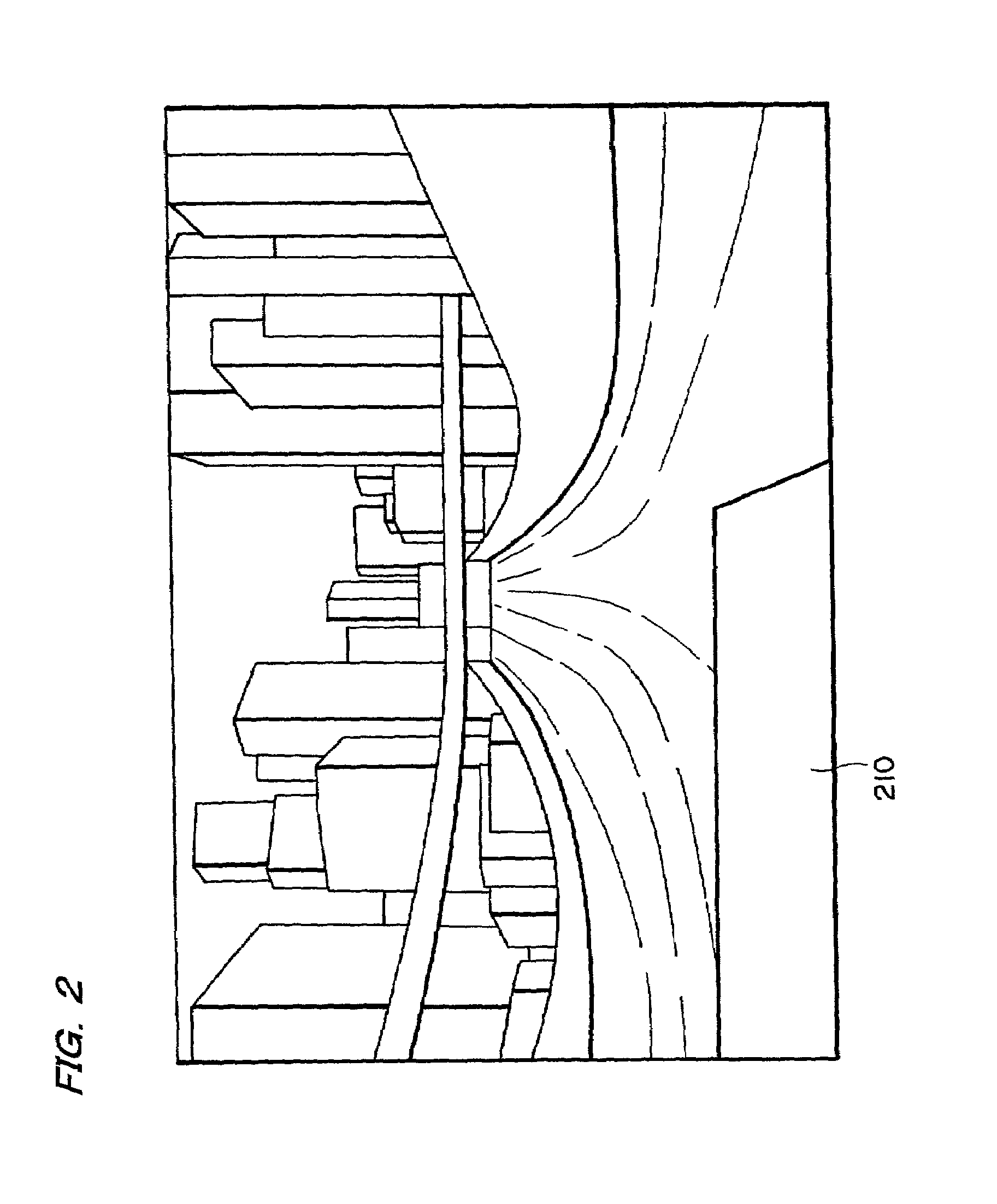
[0044]A preferred embodiment of the invention will be described with reference to the drawings. Note that the present invention will be described on the case in which it is applied to a racing game, but should not be limited thereto but could be applied to various other games.

[0045]1. Configuration

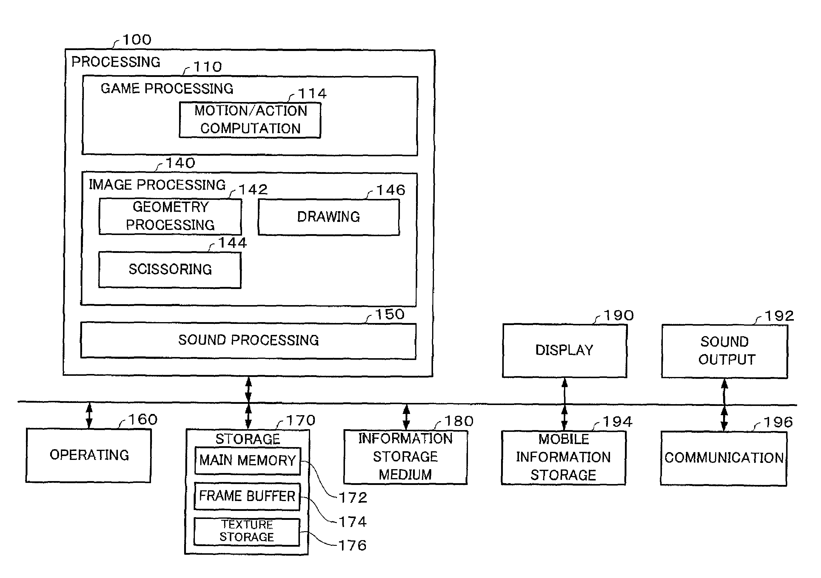
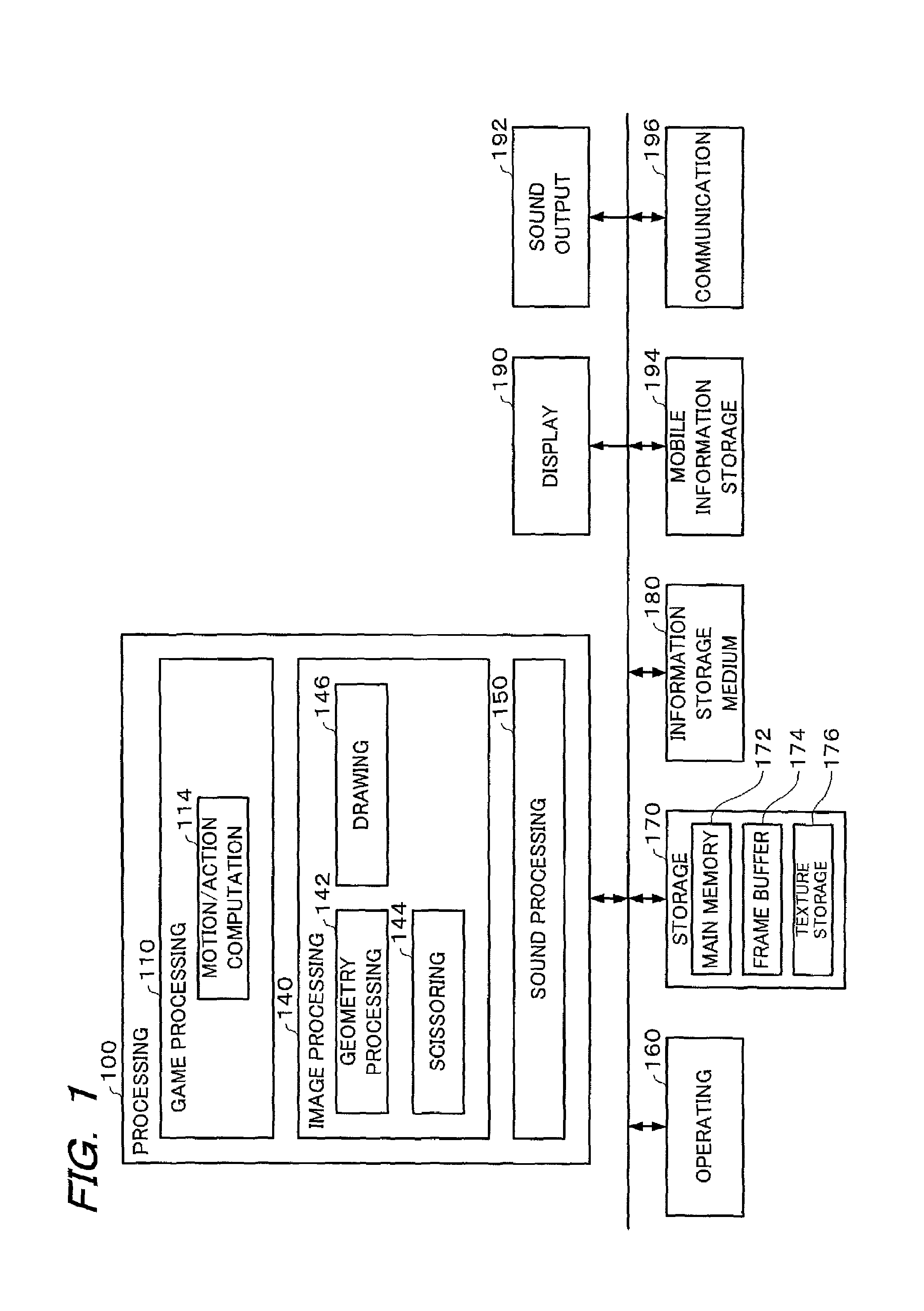
[0046]FIG. 1 shows one example of a block diagram of the embodiment. Here in FIG. 1, the embodiment may include at least a processing section 100 (or the processing section 100 and a storage section 170, or the processing section 100, the storage section 170 and an information storage medium 180), and the remaining blocks (e.g., an operating section 160, a display section 190, a sound output section 192, a portable information storage section 194 and a communication section 196) may be arbitrary components.

[0047]The processing section 100 executes various types of processing including a control of the entire system, an indication of an instruction to each block in the system, a game proces...


PUM


Abstract

An image generating system and a program enabling scissoring of a polygon in a three-dimensional stage to prevent display failure of a polygon on a screen end or at a short distance from the viewpoint with a reduced computation load. The system performs scissoring processing for a polygon in a three-dimensional stage and generates an image of an object including a new vertex generated by the scissoring. A polygon which is at a short distance from a view point, displaying of which is likely to be missed, is scissored on side surfaces of a quadrangular pyramid forming a view volume, to prevent the display failure of the polygon existing at a short distance from the end of a screen. A polygon arranged in the three-dimensional space is subjected to coordinate transformation into a screen coordinate system, to detect an undrawable vertex, and a polygon containing the detected vertex is scissored at a portion containing the detected vertex, in a predetermined plane.

Description

TECHNICAL FIELD[0001]The present invention relates to an image generating system and a program.BACKGROUND ART[0002]In the prior art, there has been known an image generating system for generating an image which can be seen from a given view point in an object space or a virtual three-dimensional space. This image generating system is highly popular because it allows the so-called “virtual reality” to be experienced. In the image generating system capable of enjoying the racing game, for example, the player enjoys the three-dimensional game by manipulating a racing car (or object) to run in the object space so that the car may compete with another racing car manipulated by another player or a computer.[0003]In this image generating system, it is an important technical target for improving the virtual reality of the player to generate a more real image.[0004]Generally in the image generation, the polygon coordinates existing in the three-dimensional space are perspectively projected a...

Claims


Application Information

Patent Timeline
Patent Type & Authority Patents(United States)
IPC IPC(8): G06T15/30A63F13/55G06T3/00G06T11/00G06T15/00
CPCG06T15/30G06T15/20A63F2300/66
Inventor TAKAHASHI, KAZUYA
Owner BANDAI NAMCO ENTERTAINMENT INC
Why Eureka
Try Eureka