Liquid crystal display device having particular alignment controlling elements in transmissive and reflective pixel regions

a liquid crystal display and controlling element technology, applied in non-linear optics, instruments, optics, etc., can solve the problems of deteriorating display quality and inability to control the tilt direction of liquid crystal molecules, and achieve the effect of suppressing display failures, wide viewing angles, and increasing the areal ratio of openings

Active Publication Date: 2006-09-12
BOE TECH GRP CO LTD
View PDF16 Cites 28 Cited by
  • Summary
  • Abstract
  • Description
  • Claims
  • Application Information

AI Technical Summary

Benefits of technology

[0013]The present invention has been accomplished to address the above problems. The present invention provides a transreflective liquid crystal display device that can suppress display failures, such as afterimages and spotting uneven displays, can produce displays with wide viewing angle and can minimize, for example, decreased aperture caused by steps in the case of providing a multi-gap structure. The present invention also provides an easy and suitable technique to control the tilt direction of liquid crystal molecules in reflective display regions and to thereby provide a liquid crystal display device that can produce uniform displays with wide viewing angles both in reflective display and transmissive display.

Problems solved by technology

If no device is provided (if pre-tilt is not applied), the tilt direction of the liquid crystal molecules cannot be controlled.
Disordered alignment (disclination) occurs to cause display failures, such as optical dropouts and to deteriorate display quality.

Method used


Image

  • Liquid crystal display device having particular alignment controlling elements in transmissive and reflective pixel regions
  • Liquid crystal display device having particular alignment controlling elements in transmissive and reflective pixel regions
  • Liquid crystal display device having particular alignment controlling elements in transmissive and reflective pixel regions

Examples


first exemplary embodiment

[0038

[0039]The first exemplary embodiment of the present invention will be illustrated below, with reference to the figures.

[0040]A liquid crystal display device according to the present exemplary embodiment is an example of an active-matrix liquid crystal display device using a thin film transistor (hereinafter briefly referred to as TFT) as a switching element.

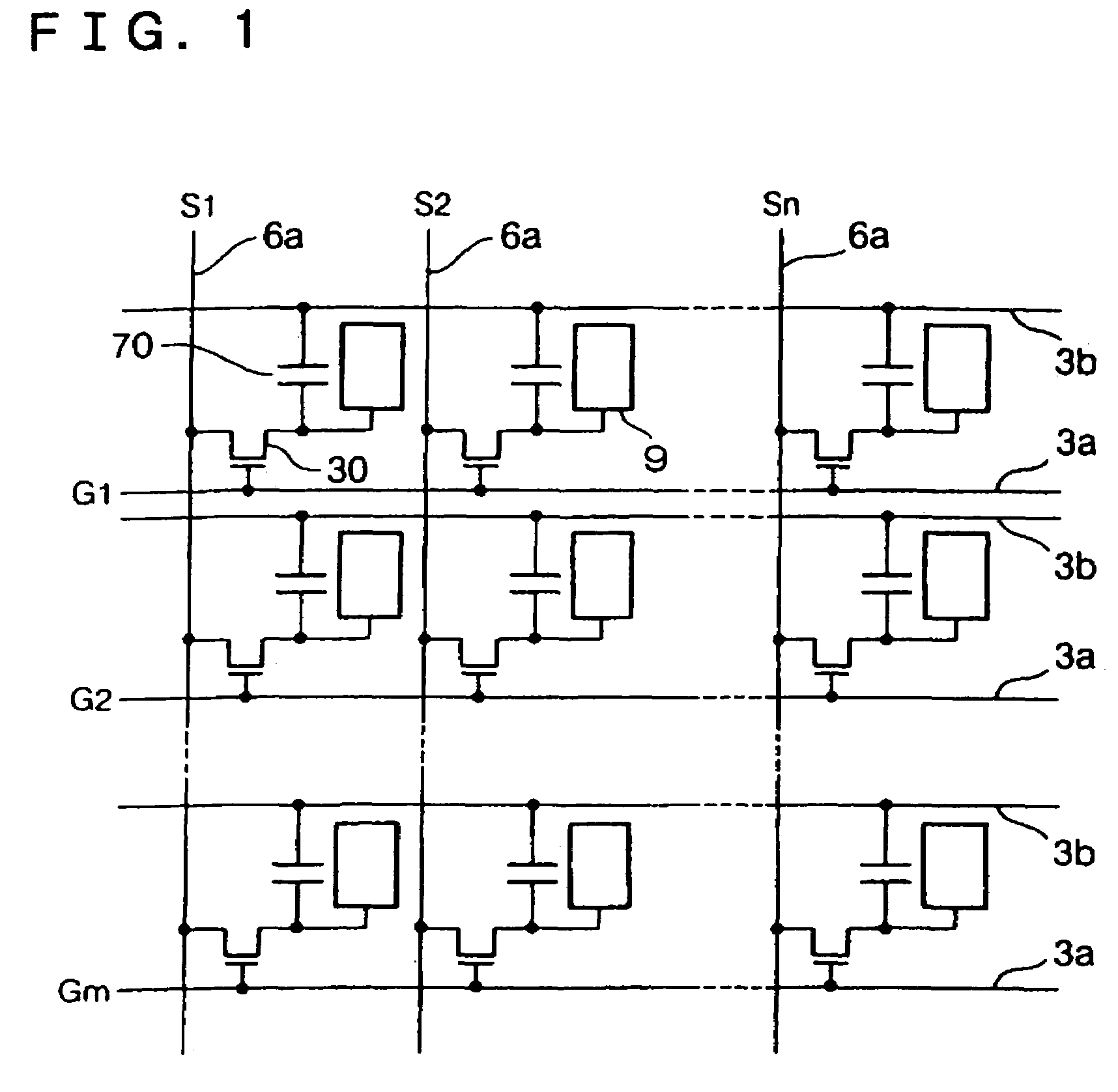
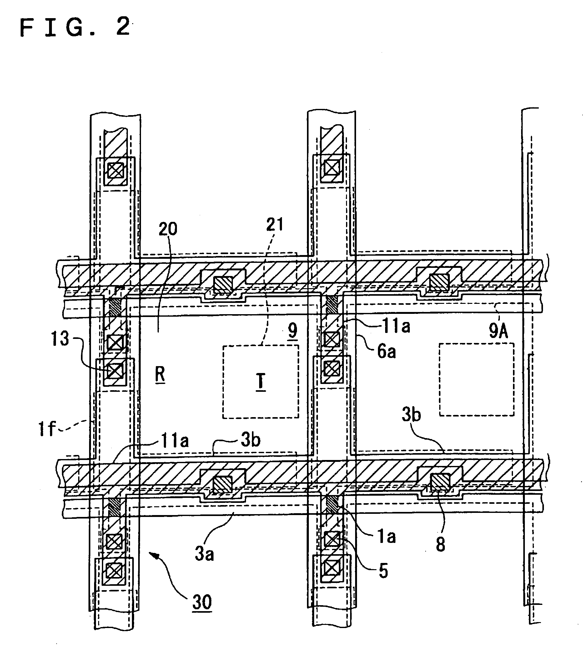
[0041]FIG. 1 is an equivalent circuit schematic of a plurality of dots arranged in a matrix constituting image display regions of the liquid crystal display device according to the present exemplary embodiment. FIG. 2 is a plan view showing the structure of adjacent plurality of dots in a TFT array substrate. FIGS. 3(A) and 3(B) are a plan view and a sectional view, respectively, of the structure of the liquid crystal device. In order to allow each layer and member to have a recognizable level of size in the figures, individual layers and members in the following figures have different reduction scales.

[0042]In the liquid cr...

second exemplary embodiment

[0066

[0067]The second exemplary embodiment of the present invention will be illustrated below, with reference to the figures.

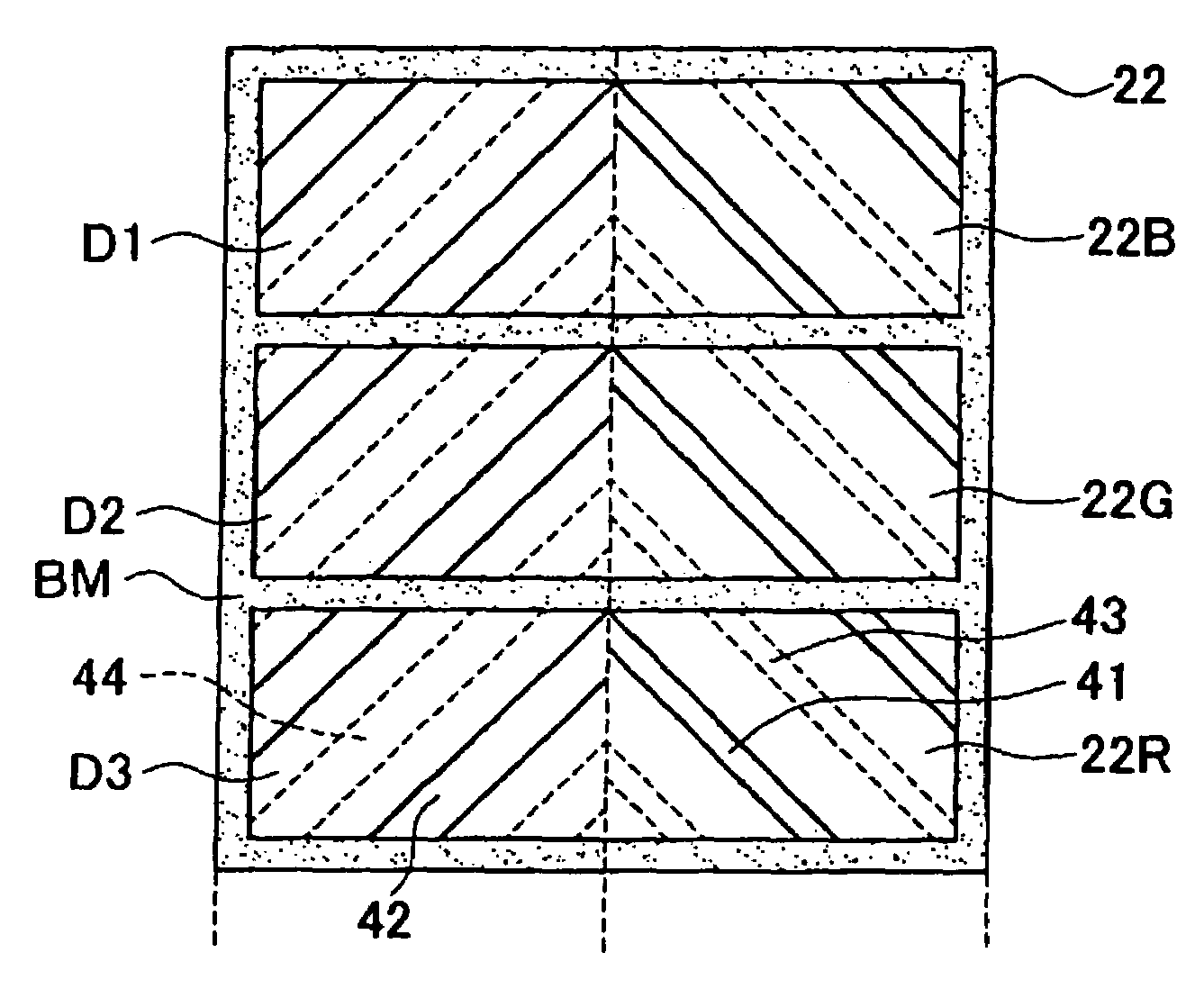
[0068]FIGS. 5(A) and 5(B) are a schematic plan view and a schematic sectional view, respectively, of a liquid crystal display device according to the second exemplary embodiment, corresponding to FIGS. 3(A) and 3(B) of the first exemplary embodiment. The liquid crystal display device of the present exemplary embodiment has a similar basic configuration to that in the first exemplary embodiment and has openings 41 and 42 arranged in reflective display regions R and transmissive display regions T of a pixel electrode 9, and protrusions 43 and 44 in reflective display regions R and transmissive display regions T of a common electrode 31. However, the second exemplary embodiment differs from the first exemplary embodiment in that a resinous insulating film 24 is not arranged in the transmissive display regions T, namely, an insulating film 24 having an uneven surf...

third exemplary embodiment

[0072

[0073]The third exemplary embodiment of the present invention will be illustrated below, with reference to FIGS. 6A) and 6(B).

[0074]FIGS. 6(A) and 6B) are a schematic plan view and a schematic sectional view, respectively, of a liquid crystal display device according to the third exemplary embodiment, corresponding to FIGS. 3(A) and 3(B) of the first exemplary embodiment. The liquid crystal display device of the present exemplary embodiment differs from the first exemplary embodiment in that a common electrode (counter electrode) 31 on a counter substrate 25 has no protrusions, and that a reflective display region R and a transmissive display region T both have openings 45 and 46. The other configuration is substantially equal to the first exemplary embodiment. Accordingly, the same components in FIGS. 6(A) and 6(B) as in FIGS. 3(A) and 3(B) have the same reference numerals and detailed description thereof is omitted.

[0075]In the present exemplary embodiment, the openings arran...


PUM

PropertyMeasurementUnit
widthaaaaaaaaaa
widthaaaaaaaaaa
widthaaaaaaaaaa

Abstract

To provide a transreflective liquid crystal display device that can produce a bright and high-contrast display with a wide viewing angle. A liquid crystal display device has a liquid crystal layer held between a pair of substrates and has a transmissive display region and a reflective display region in one dot region. The liquid crystal layer includes a liquid crystal being initially vertically aligned and having negative dielectric anisotropy. The pair of substrates have electrodes to drive the liquid crystal on sides facing the liquid crystal layer. The electrodes have openings and protrusions in the transmissive display region and the reflective display region, respectively. The opening areas of the openings and the in-plane occupying areas of the protrusions are larger in the reflective display region than in the transmissive display region.

Description

BACKGROUND OF THE INVENTION[0001]1. Field of Invention[0002]The present invention relates to a liquid crystal display device and electronic equipment, and specifically, it relates to a technique to produce a display with a high contrast and a wide viewing angle in a transreflective liquid crystal display device that produces displays both in reflective mode and transmissive mode.[0003]2. Description of Related Art[0004]Certain transreflective liquid crystal display devices working both in reflective mode and transmissive mode are known as liquid crystal display devices. Among such related art transreflective liquid crystal display devices, one including an upper substrate, a lower substrate, and a liquid crystal layer held between the upper and lower substrates and having a reflective film on an inner surface of the lower substrate has been proposed. In this device, the reflective film includes a film of metal, such as aluminum, has a window for optical transmission and functions as...

Claims


Application Information

Patent Timeline
Patent Type & Authority Patents(United States)
IPC IPC(8): G02F1/1337G02F1/1335G02F1/1333G02F1/13357G02F1/1343G02F1/139
CPCG02F1/133555G02F1/1393G02F1/133707G02F1/1335
Inventor OKUMURA, OSAMU
Owner BOE TECH GRP CO LTD
Why Eureka
Try Eureka