Cooling system and method employing multiple dedicated coolant conditioning units for cooling multiple electronics subsystems

a technology for electronics subsystems and cooling systems, applied in domestic cooling apparatus, semiconductor/solid-state device details, instruments, etc., can solve problems such as all frames losing conditioned water, and bringing down the entire computer room floor

Inactive Publication Date: 2006-09-12
INT BUSINESS MASCH CORP
View PDF14 Cites 183 Cited by
  • Summary
  • Abstract
  • Description
  • Claims
  • Application Information

AI Technical Summary

Benefits of technology

[0010]These shortcomings are overcome and additional advantages are provided through the provision of a cooling system having multiple coolant conditioning units (CCUs). Each CCU of at least some coolant conditioning units of the multiple CCUs provide system coolant to a different, associated electronics subsystem of multiple electronics subsystems to be cooled. Each CCU of the at least some CCUs comprises a heat exchanger, a first cooling loop with a control valve, and a second cooling loop. The first cooling loop receives chilled facility coolant from a source and passes at least a portion thereof via the control valve through the heat exchanger. The second cooling loop provides cooled system coolant to an associated electronics subsystem, and expels heat in the heat exchanger from the associated electronics subsystem to the chilled facility coolant in the first cooling loop. The control valve allows regulation of chilled facility coolant flow through the heat exchanger, thereby allowing independent control of temperature of the system coolant in the second cooling loop.
[0011]In another aspect, a cooled electronics system is provided. The cooled electronics system includes multiple electronics subsystems, and multiple coolant conditioning units (CCUs). Each CCU provides system coolant to a different, associated electronics subsystem of the multiple electronics subsystems. Each CCU includes a heat exchanger, a first cooling loop with a control valve, and a second cooling loop. The first cooling loop receives chilled facility coolant from a source and passes at least a portion thereof via the control valve through the heat exchanger. The second cooling loop provides cooled system coolant to the associated electronics subsystem, and expels heat in the heat exchanger from the associated electronics subsystem to the facility coolant in the first cooling loop. The control valve allows regulation of the chilled facility coolant flow through the heat exchanger, and thus, allows independent control of temperature of the system coolant in the second cooling loop for cooling the electronics subsystem associated with the CCU.

Problems solved by technology

Therein lies a problem, however.
Any leak in any of the processor frames could cause all of the frames to lose conditioned water.
A single leak could bring down the entire computer room floor.
Also, a heat exchanger failure or control valve failure or loss of chilled water source could bring down the entire computer room floor.

Method used


Image

  • Cooling system and method employing multiple dedicated coolant conditioning units for cooling multiple electronics subsystems
  • Cooling system and method employing multiple dedicated coolant conditioning units for cooling multiple electronics subsystems
  • Cooling system and method employing multiple dedicated coolant conditioning units for cooling multiple electronics subsystems

Examples


Embodiment Construction

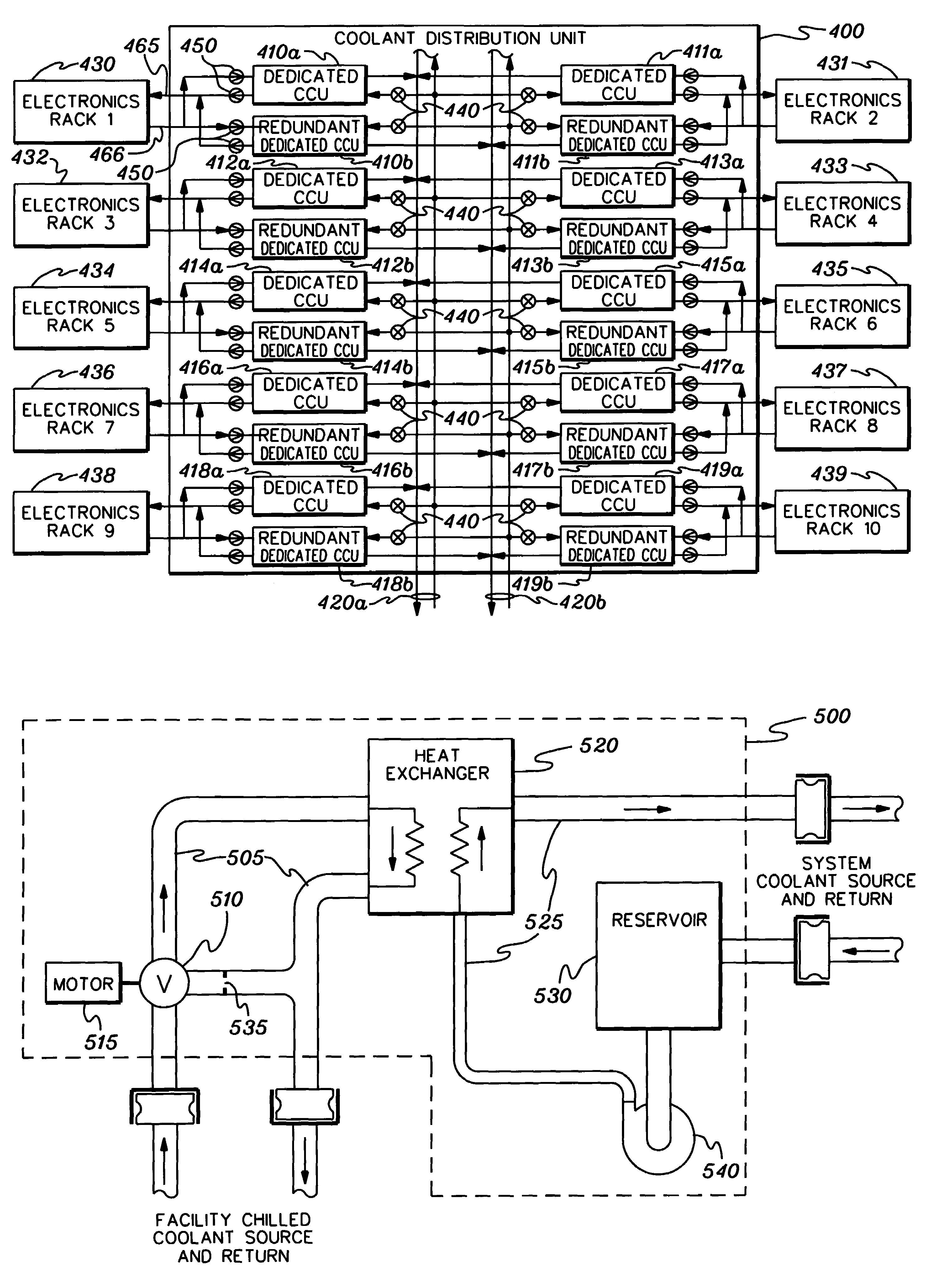
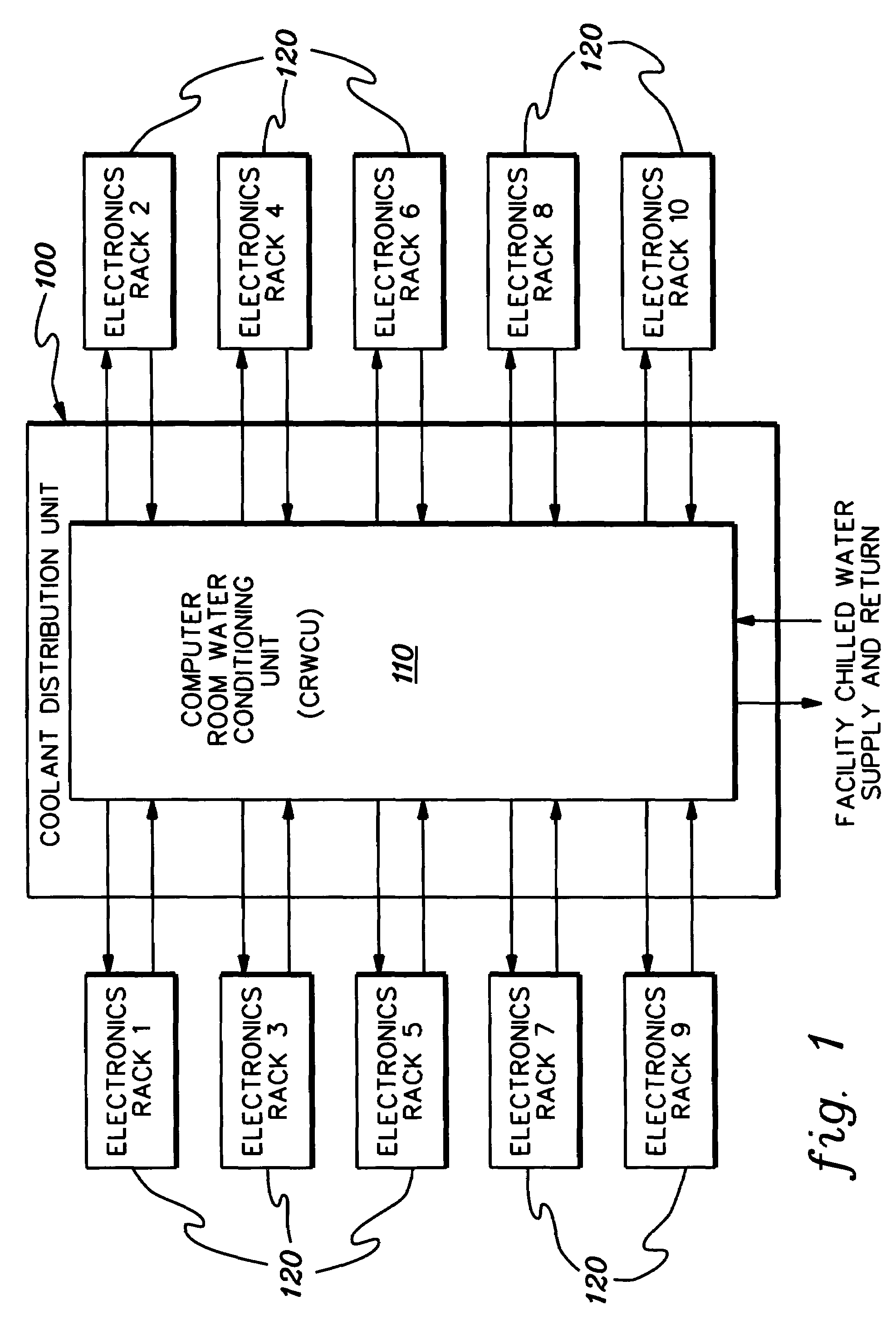
[0025]As used herein “electronics subsystem” comprises any housing, frame, rack, compartment, etc., containing one or more heat generating components of a computer system or other electronics system requiring cooling. The term “electronics rack” includes any frame or rack having a heat generating component of a computer system or electronics system; and may be, for example, a stand alone computer processor having high, mid or low end processing capability. In one embodiment, an electronics rack may comprise multiple electronics drawers, each having one or more heat generating components requiring cooling.

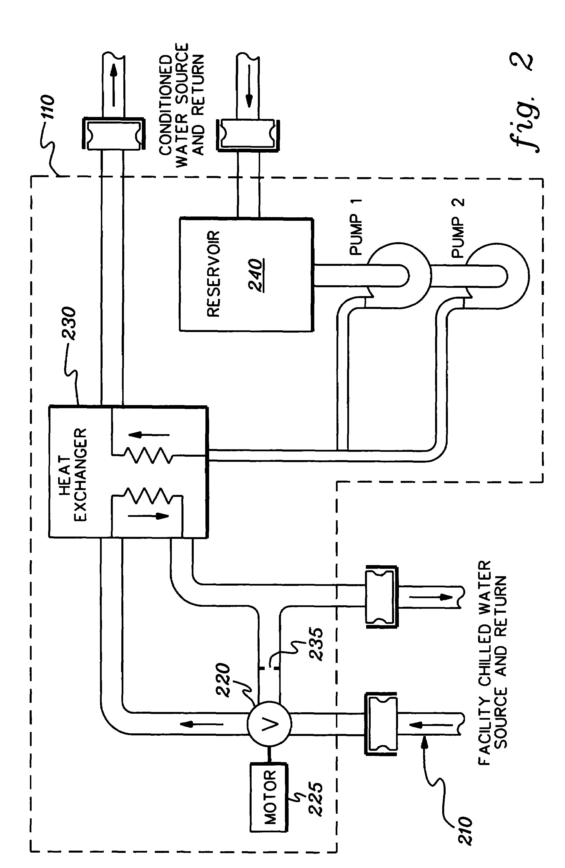
[0026]One example of coolant within the coolant distribution unit, or more particularly within the multiple coolant conditioning units (CCUs) described herein, is water. However, the concepts disclosed are readily adapted to use with other types of coolant on both the facility side and the system side. For example, the coolant may comprise a brine, a fluorocarbon liquid, or other si...


PUM


Abstract

A cooling system is provided employing multiple coolant conditioning units (CCUs). Each CCU, which is coupled to a different, associated electronics rack of multiple electronics racks to be cooled, includes a heat exchanger, a first cooling loop with a control valve, and a second cooling loop. The first cooling loop receives chilled facility coolant from a source and passes at least a portion thereof via the control valve through the heat exchanger. The second cooling loop provides cooled system coolant to the associated electronics rack, and expels heat in the heat exchanger from the electronics rack to the chilled facility coolant in the first cooling loop. The control valve allows regulation of the facility coolant flow through the heat exchanger, thereby allowing independent control of temperature of the system coolant in the second cooling loop. Various CCU and associated component redundancies of the cooling system are also provided.

Description

CROSS REFERENCE TO RELATED APPLICATIONS[0001]This application contains subject matter which is related to the subject matter of the following applications, each of which is assigned to the same assignee as this application and each of which is hereby incorporated herein by reference in its entirety:[0002]“Cooling System and Method Employing At Least Two Modular Cooling Units For Ensuring Cooling Of Multiple Electronics Subsystems,” Chu et al., Ser. No. 10 / 726,377, filed Dec. 3, 2003; and[0003]“Scalable Coolant Conditioning Unit with Integral Plate Heat Exchanger / Expansion Tank and Method of Use,” Chu et al., Ser. No. 10 / 243,708, filed Sep. 13, 2002, which issued on Mar. 30, 2004 as U.S. Pat. No. 6,714,412.TECHNICAL FIELD[0004]The present invention relates in general to cooling assemblies and other apparatus used for removing heat from electronic devices, modules and systems. More particularly, this invention relates to cooling systems and methods for liquid cooling of electronics su...

Claims


Application Information

Patent Timeline
Patent Type & Authority Patents(United States)
IPC IPC(8): H05K7/20F28D15/00G06F1/20H01L23/473
CPCH05K7/2079
Inventor CHU, RICHARD C.ELLSWORTH, JR., MICHAEL J.SCHMIDT, ROGER R.SIMONS, ROBERT E.ZOODSMA, RANDY J.
Owner INT BUSINESS MASCH CORP
Why Eureka
Try Eureka