Tuneable laser

a laser and tuning technology, applied in the direction of laser details, laser optical resonator construction, optical resonator shape and construction, etc., can solve the problems of reducing the output power of the laser, short wavelength loss, limiting the total optical bandwidth, etc., and achieve acceptable manufacturing costs and high optical output power.

Inactive Publication Date: 2006-09-12
LUMENTUM TECH UK LTD
View PDF12 Cites 14 Cited by
  • Summary
  • Abstract
  • Description
  • Claims
  • Application Information

AI Technical Summary

Benefits of technology

[0009]The present invention seeks to provide a tuneable laser with a...

Problems solved by technology

In practice, the reflection spectra of the known sampled grating structures have a sine squared envelope which limits the total optical bandwidth over which the laser can reliably operate as a single mode device.
A...

Method used


Image

  • Tuneable laser
  • Tuneable laser
  • Tuneable laser

Examples


Embodiment Construction

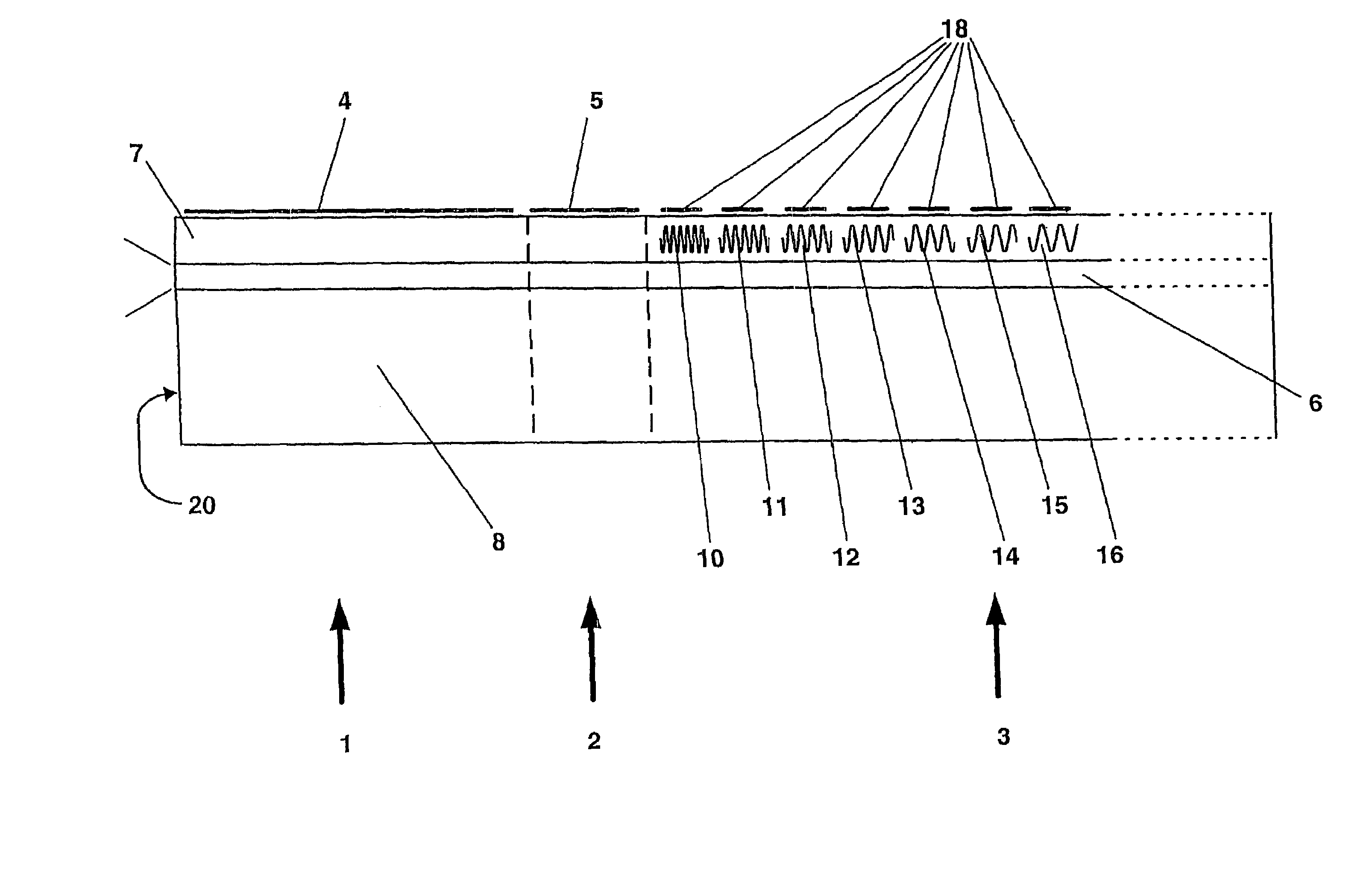
[0028]The wavelengths of interest referred to above, for example the C-band wavelengths of 1530 to 1570 nm are the wavelengths of light in free space. When such light passes through a medium, of refractive index neff the wavelength of the light changes. The actual wavelength of the light within that medium which will be referred to herein as λ′, is the wavelength λ divided by the value for the refractive index neff. In other words

λ′=λ / neff.

where neff is the effective refractive index of the medium as seen by the propagating light.

[0029]It so happens that the glass (silica) fibres, which are commonly used in telecommunications systems, have low loss regions at about 1100 nm 1300 nm and 1500 nm. These regions are about 100 nm wide and consequently much work is done on producing lasers that produce light in the low loss regions. The same is true for the tuneable laser of the present invention. The specific examples of the invention are designed to work in the C-Band, but the invention ...


PUM


Abstract

A tuneable laser having an active section, a phase section and a Bragg reflector comprising a plurality of discrete grating units, at least two of which gratings have a different pitch, wherein current is applicable to at least the grating having a longer pitch, such that the effective wavelength of the grating having a longer pitch can be tuned to the wavelength of the grating having a shorter pitch. A chirp grating can provide the difference in pitch.

Description

RELATED APPLICATIONS[0001]This application is a 35 U.S.C. 371 national stage filing of International Application No. PCT / GB02 / 01329, filed 19 Mar. 2002, which claims priority to Great Britain Patent Application No. 0106790.9 filed on 19 Mar. 2001, and Great Britain Patent Application No. 0114970.7 filed on 19 Jun. 2001 in Great Britain. The contents of the aforementioned applications are hereby incorporated by reference.FIELD OF THE INVENTION[0002]This invention relates to a tuneable laser, in particular but not exclusively to a three section distributed Bragg reflector tuneable laser.BACKGROUND OF THE INVENTION[0003]Tuneable lasers are well known in the field of optical communications, particularly in connection with wavelength division multiplex telecommunication systems, which rely upon either being fed by stacks of individually wavelength distributed Bragg reflectors (DBR) lasers, which can be individually selected, or by a wide tuning range tuneable laser that can be electronic...

Claims


Application Information

Patent Timeline
IPC IPC(8): H01S3/08H01S5/0625H01S5/12
CPCH01S5/06256H01S5/1215H01S5/1212
Inventor REID, DOUGLAS CHARLES JOHNCARTER, ANDREW CANNON
Owner LUMENTUM TECH UK LTD
Why Eureka
Try Eureka