Mobile communication terminal, communication method and program

a mobile communication terminal and communication method technology, applied in the field of communication technology for mobile communication terminals, can solve the problems of inability of the base station to generate a directivity pattern, transmission signals in the same frame cannot reach the base station, and the mobile communication terminal cannot receive signals properly from the base station, so as to achieve the effect of higher probability of transmission signals and higher reception quality

Inactive Publication Date: 2006-09-12
HERA WIRELESS
View PDF12 Cites 33 Cited by
  • Summary
  • Abstract
  • Description
  • Claims
  • Application Information

AI Technical Summary

Benefits of technology

[0021]With the stated construction, there is a higher probability of transmission signals reaching an intended

Problems solved by technology

However, due to problems such as weak electrical fields, interference and losses of synchronization, there are cases where the mobile communication terminal cannot receive signals properly from the base station.
In this case, transmission signals in the same frame will not be able to reach the base station with which the mobile communication terminal is communicating.
This also makes it impossible for

Method used


Image

  • Mobile communication terminal, communication method and program
  • Mobile communication terminal, communication method and program
  • Mobile communication terminal, communication method and program

Examples


first embodiment

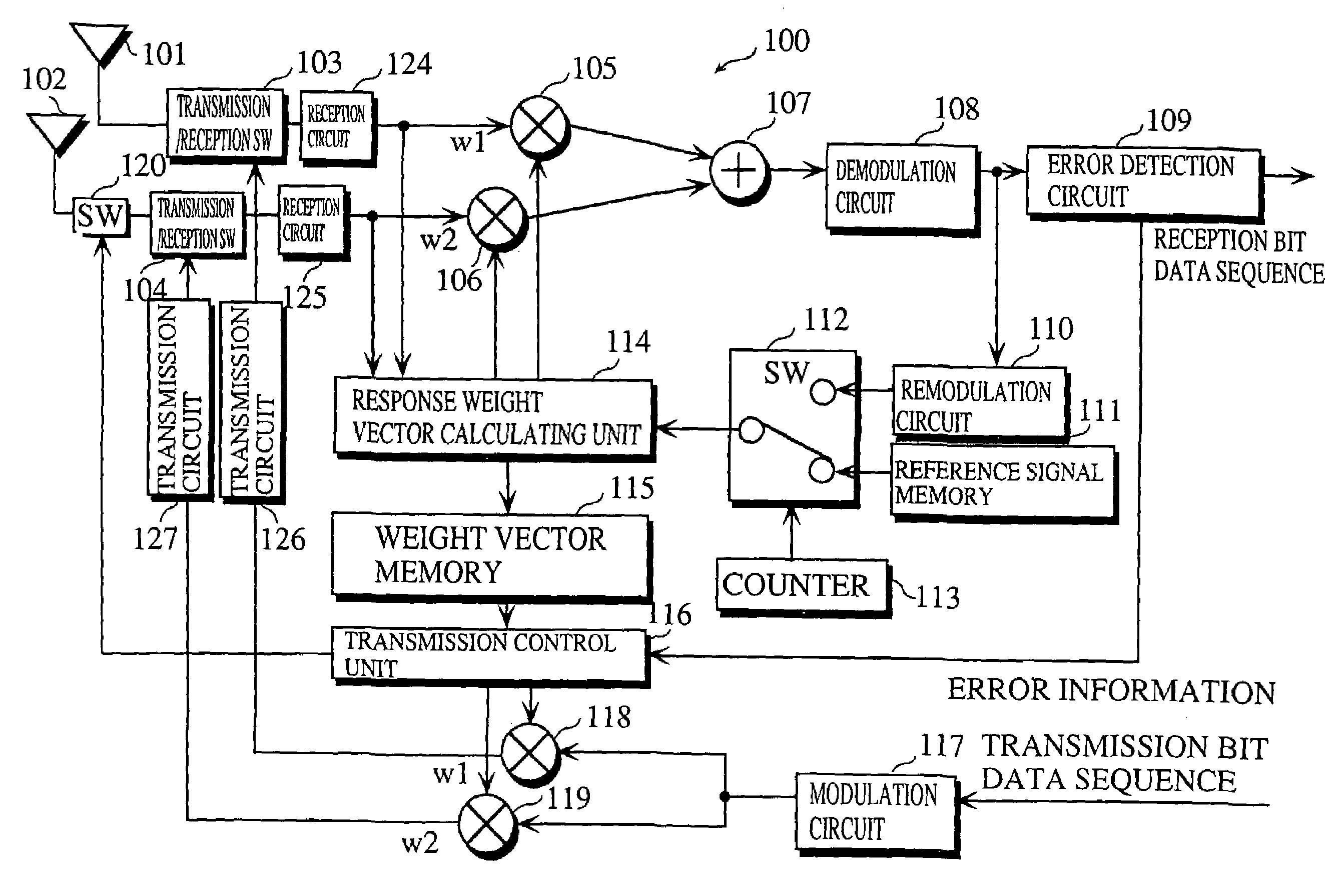
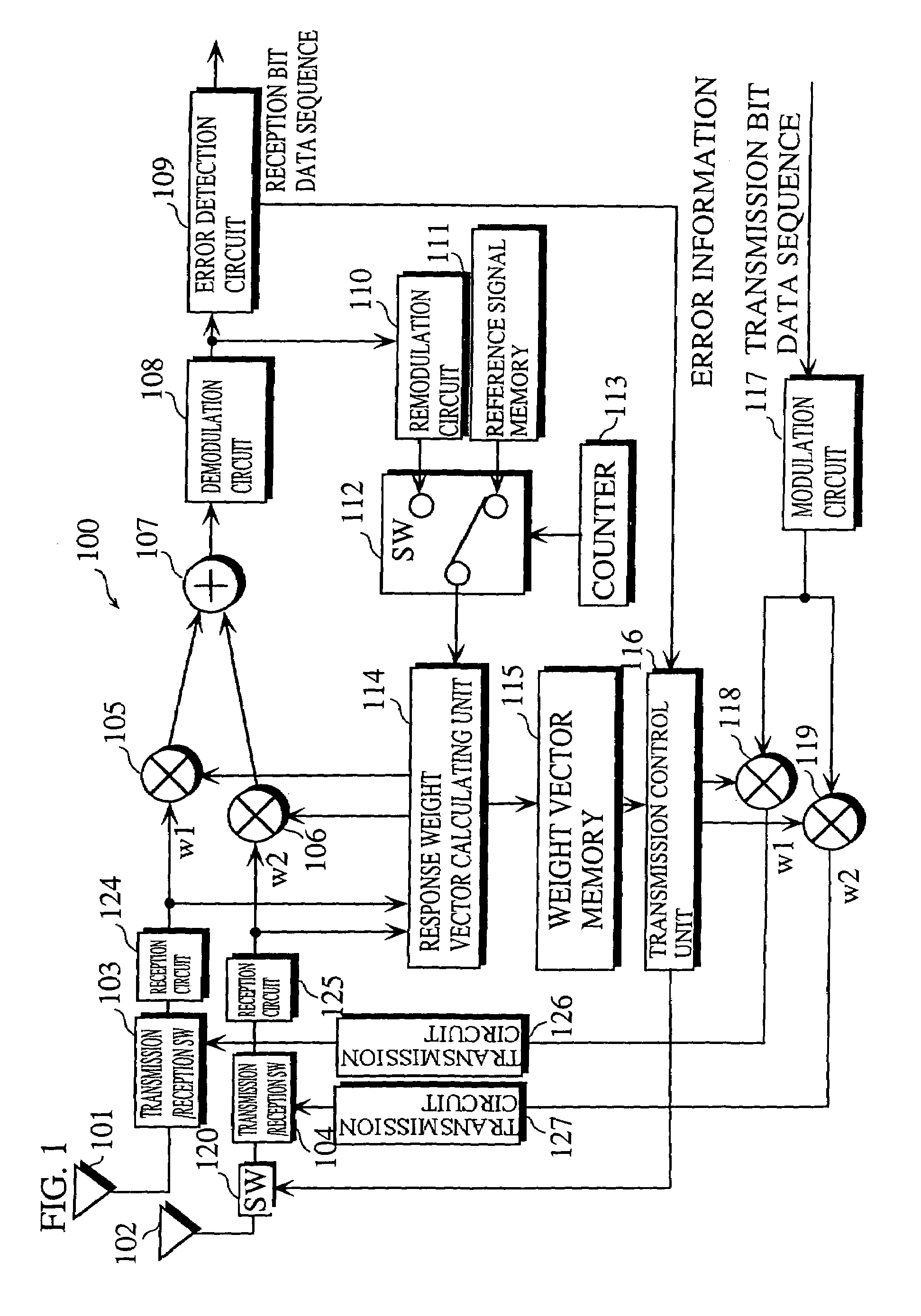
[0030]FIG. 1 is a block diagram showing a main construction of a mobile communication terminal in the first embodiment of the invention.

[0031]As shown in FIG. 1, a mobile communication terminal 100 includes antennas 101 and 102, reception circuits 124 and 125, transmission / reception switches 103 and 104, multipliers 105 and 106, an adder 107, a demodulation circuit 108, an error detection circuit 109, a remodulation circuit 110, a reference signal memory 111, a switch 112, a counter 113, a response weight vector calculating unit 114, a weight vector memory 115, a transmission control unit 116, a modulation circuit 117, multipliers 118 and 119 and a switch 120.

[0032]The antenna 101 is a rod antenna and the antenna 102 is a tip antenna which is provided on a substrate inside the mobile communication terminal 100.

[0033]The transmission / reception switches 103 and 104 switch between reception and transmission.

[0034]The reception circuits 124 and 125 convert high frequency signals receive...

second embodiment

[0065]The following describes a mobile communication terminal in the second embodiment of the invention.

[0066]FIG. 5 is a block diagram showing the construction of the mobile communication terminal in the present embodiment.

[0067]As shown in FIG. 5, a mobile communication terminal 200 differs from the mobile communication terminal 100 of FIG. 1 in that it includes a reception level measuring unit 123, switches 121 and 122 in place of the switch 120, and a transmission control unit 129 in place of the transmission control unit 116. Construction elements which are the same as those shown in FIG. 1 are given the same reference numerals, and their explanation is omitted here. The following description focuses on the differences with the first embodiment.

[0068]The reception level measuring unit 123 measures reception levels R1 and R2 of signals received from the reception circuits 124 and 125, and outputs them to the weight vector memory 128. The reception levels R1 and R2 indicate recep...


PUM


Abstract

A mobile communication terminal having adaptive array antennas is provided that is capable of transmitting signals to an intended base station without interfering other devices, even when a reception error occurs. The mobile communication terminal basically performs array transmission/reception using weight vectors produced in reception to weight and combine signals received via antennas, and thereby receives a desired signal. In transmission, the mobile communication terminal uses the weight vectors used in reception to weight and combine transmission signals and transmits them. However, when an error detection circuit detects a reception error in the desired signal, a transmission control unit turns off a switch for the antenna and transmits the transmission signals in a non-directional pattern via the antenna, so that the transmission signal reaches the intended base station.

Description

[0001]This application is based on an application No. 2000-215099 filed in Japan, the content of which is hereby incorporated by reference.BACKGROUND OF THE INVENTION[0002]1. Field of the Invention[0003]The present invention relates to a communication technology for a mobile communication terminal that uses an adaptive array antenna.[0004]2. Related Art[0005]In recent years, increasing attention has been given to the adaptive array method in the field of mobile communication to make efficient use of frequencies and improve communication quality. The adaptive array method is a communication method that performs transmission / reception by adjusting a signal amplitude and phase for each of a plurality of antennas, thereby enhancing a radiant intensity or reception sensitivity with regard to a direction from which a desired signal comes.[0006]A mobile communication system that uses the adaptive array method employs a communication technology in which a base station, equipped with an adap...

Claims


Application Information

Patent Timeline
IPC IPC(8): H04M1/00H04B7/06H04B7/08
CPCH04B7/0814H04B7/061H04B7/06H04B7/08H04W88/02
Inventor DOI, YOSHIHARU
Owner HERA WIRELESS
Why Eureka
Try Eureka