Studded footwear

a technology of studs and shoes, applied in the field of studs, can solve the problems of inability to predict the final position, inability to provide precise orientation of threads and locking ratchets, time-consuming operation of removal and replacement of single start threads, etc., and achieve the effect of positive initial orientation of the studs and strengthening the connection

Inactive Publication Date: 2006-09-19
TRISPORT
View PDF170 Cites 45 Cited by
  • Summary
  • Abstract
  • Description
  • Claims
  • Application Information

AI Technical Summary

Benefits of technology

[0019]The locking means preferably comprises radially facing locking formations on the stud and receptacle operative to come into mutual engagement when the spigot has been screwed into the socket to a predetermined axial position. One of the locking formations comprises at least one radial projection, while the other comprises at least a radially-facing lead-in ramp, recess and stop means. The projection rides over a lead-in ramp before snapping into a recess, and then engages the stop means to prevent the stud from being screwed any further into the socket. The locking means allows the stud to be unscrewed in response to application of a predetermined torque by resili

Problems solved by technology

However, because of the number of turns needed to attach and detach the stud, removal and replacement with a single start thread becomes a time-consuming operation.
In fact, currently most studs are circular or otherwise rotationally symmetrical, and their final rotational or angular orientation relative to

Method used


Image

  • Studded footwear
  • Studded footwear
  • Studded footwear

Examples


Embodiment Construction

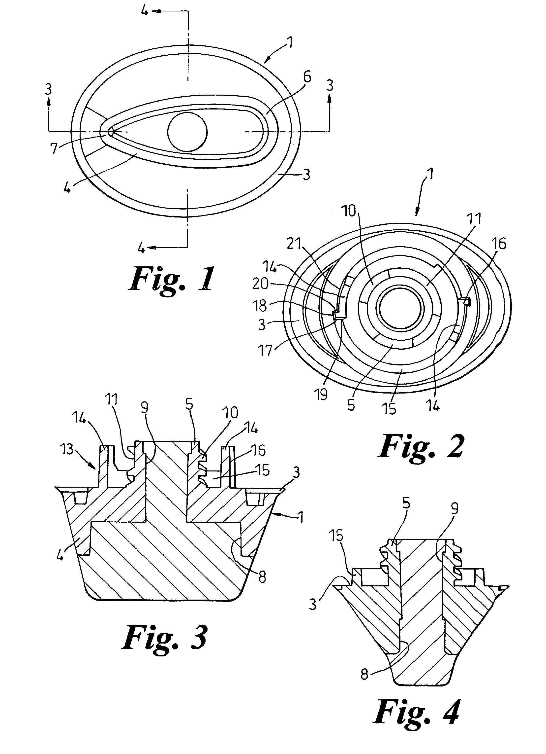
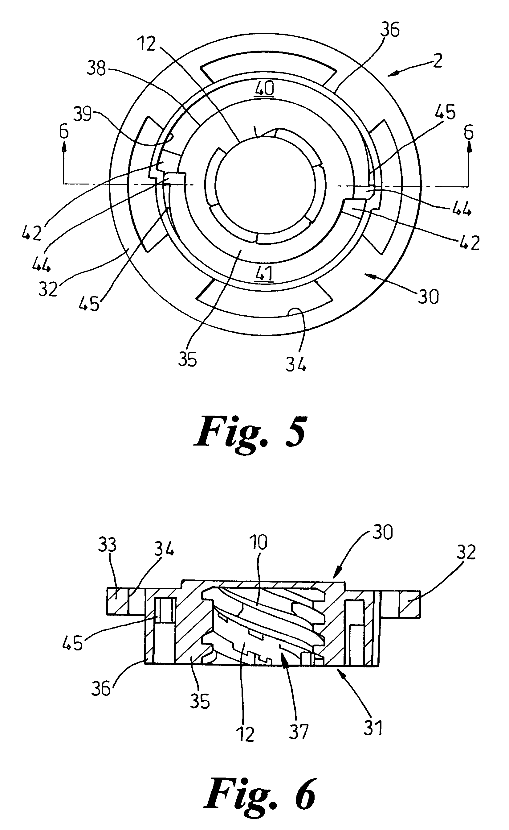
[0046]FIGS. 1 to 4 show a stud 1 suitable for use on a sports shoe such as a football boot (not shown). The stud 1 is adapted to be inserted with rotation and received in a receptacle 2, shown in FIGS. 5 and 6, which is moulded into or otherwise attached to a sole or heel of the sports shoe.

[0047]The stud 1 is a unitary (i.e., one piece) melding of plastics material and has an elliptical flange 3. A ground-engaging spike or cleat 4 projects from the lower side of the flange 3, while an externally screw-threaded spigot 5 projects from the upper side. FIG. 1 shows the spike 4 to be of non-rotationally symmetrical form, being elongated along the major axis of the flange 3, rounded at one end 6, and tapering to a point at the other end 7. The spike 4 has a recess 8 at its ground-engaging end, and a plain cylindrical bore 9 extends from the recess 8 up through the spigot 5. An appropriate part is inserted in the recess 8 and bore 9 to complete the stud 1. It will be appreciated that the ...


PUM


Abstract

A shoe stud for a sports shoe has a ground-engaging part and a multi-start threaded spigot for engagement in a complementary socket on a receptacle secured in the shoe sole or heel. The stud and receptacle also have a locking device which inter-engages when the spigot is fully inserted into the socket, to resist unscrewing. In order to ensure that the stud takes up a precise position relative to the receptacle, which may be needed if the stud is not rotationally symmetrical, the stud and receptacle have means to determine the initial position of the stud relative to the receptacle, and means to determine the final position of the stud relative to the receptacle. Determination of the initial position may be provided by a thread and complementary groove of the screw-thread connection which are of different dimensions from the others.

Description

CROSS-REFERENCE TO RELATED APPLICATION[0001]This application is a continuation of application Ser. No. 09 / 987,238, filed Nov. 14, 2001 now U.S. Pat. No. 6,823,613, the entire content of which is hereby incorporated by reference.[0002]This application is a continuation of and relies for priority on prior U.S. Provisional Patent application Ser. No. 60 / 249,461, filed Nov. 20, 2000, the entire disclosure of which is incorporated herein by reference.BACKGROUND OF THE INVENTION[0003]1. Technical Field[0004]This invention relates to studded footwear such as sports shoes, for example football boots track and field shoes, golf shoes, and footwear for other sports. The term “football” is intended to encompass all sports known as football, such as soccer, rugby and American and Australian football.[0005]2. Discussion of Known Art[0006]The studs of the present invention are intended to provide traction, having a ground-engaging part of a type suited to the sport involved. Thus, studs for footb...

Claims


Application Information

Patent Timeline
IPC IPC(8): A43B5/02A43C15/16A23C15/16A43B5/00A43B13/26A43CA43C15/00
CPCA43C15/161
Inventor KELLY, PAUL ANDREWSHUTTLEWORTH, LEE PAUL
Owner TRISPORT
Why Eureka
Try Eureka