Endotracheal tube using leak hole to lower dead space

a tracheal tube and dead space technology, applied in the field of medical devices, can solve the problems of reducing the lumen, reducing the oxygen flow to the body, and reducing the patient's breathing difficulty, so as to reduce the resistance of the airway, reduce the dead space, and remove the effect of expired gases

Inactive Publication Date: 2006-09-19
HEALTH & HUMAN SERVICES THE GOVERNMENT OF THE US SEC THE DEPT OF
View PDF24 Cites 39 Cited by
  • Summary
  • Abstract
  • Description
  • Claims
  • Application Information

AI Technical Summary

Benefits of technology

[0006]The present invention provides a tracheal tube ventilation apparatus to more effectively remove expired gases and thereby lower dead space. In one preferred embodiment, this is accomplished by creating one or more leak holes in the wall of the endotracheal tube above the larynx, such as in the back of the mouth (i.e., oropharynx), so that expired gases can leak out of the endotracheal tube. Each leak hole might advantageously have a diameter between 0.5 and 4.0 mm. In another preferred embodiment, a

Problems solved by technology

Through injury or diseases, human or animal lungs can become too weak to sustain a sufficient flow of oxygen to the body and to remove adequate amounts of expired carbon dioxide.
One of the drawbacks of inserting an endotracheal tube and/or catheter into the trachea of a patient is that it reduces the lumen of the tracheal pass

Method used


Image

  • Endotracheal tube using leak hole to lower dead space
  • Endotracheal tube using leak hole to lower dead space
  • Endotracheal tube using leak hole to lower dead space

Examples


Embodiment Construction

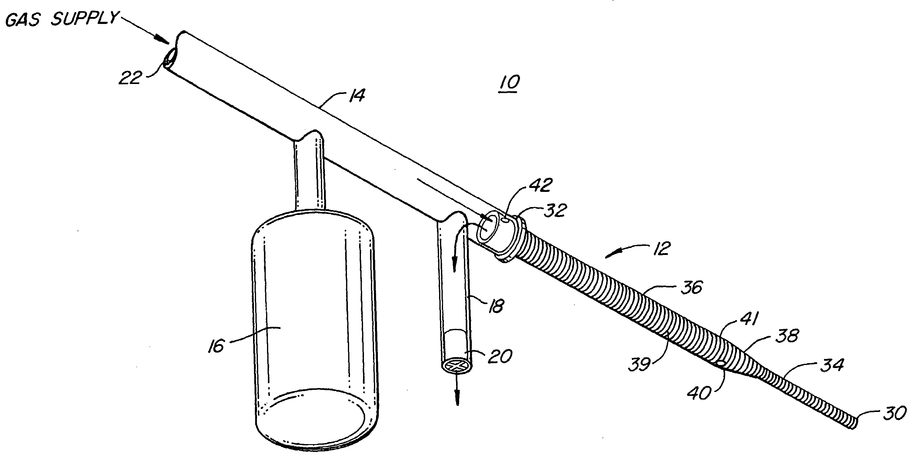
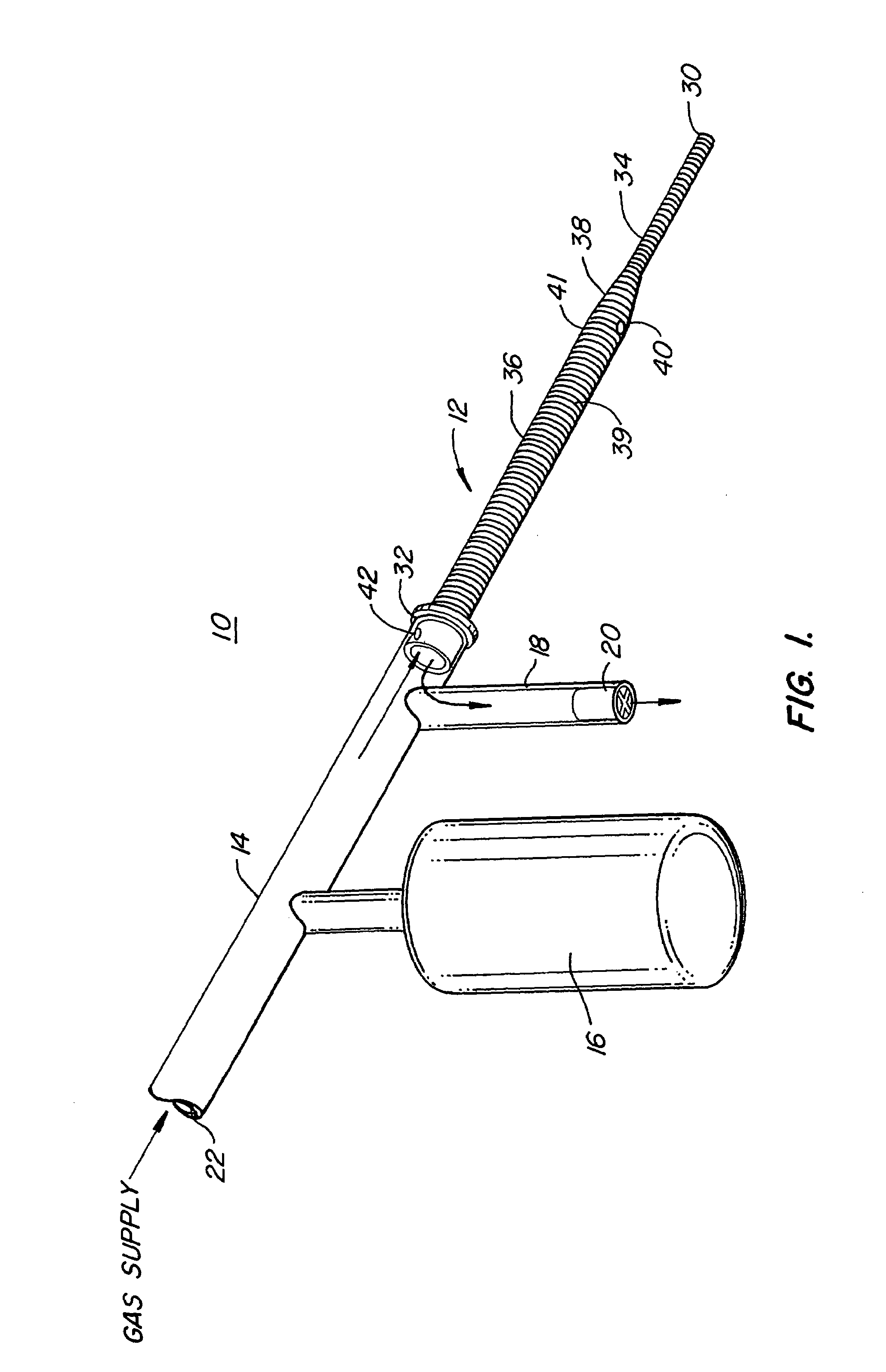
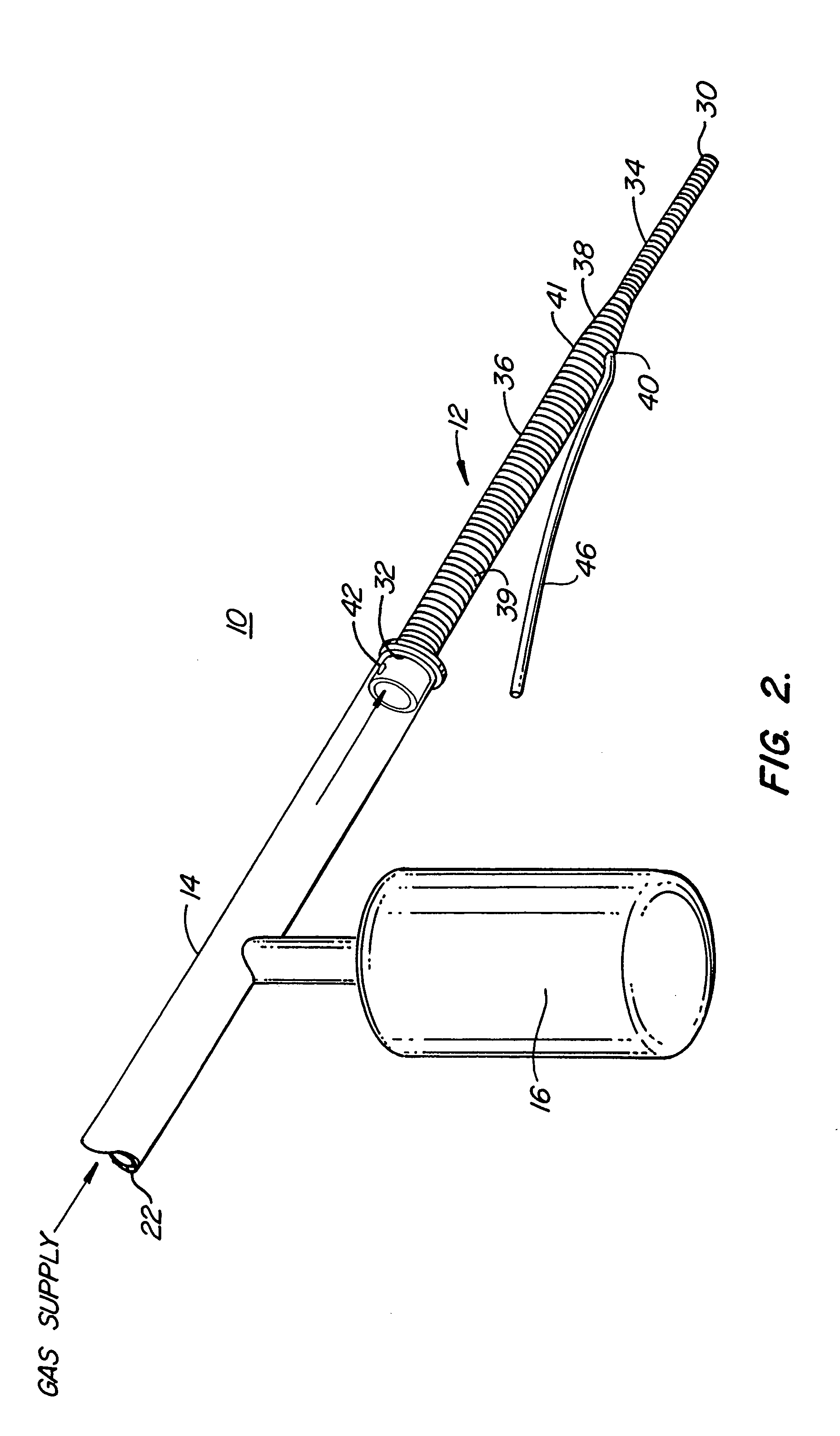
[0010]FIG. 1 shows a tracheal tube ventilation apparatus 10 for CPAP ventilation which is constructed in accordance with the present invention. This tracheal tube ventilation apparatus 10 includes an endotracheal tube 12, a flexible exterior tube 14, a balloon reservoir 16 and a safety tube 18 with threshold valve 20. Through use of a gas supply to the proximal end 22 of the flexible exterior tube 14 and a continuously leaking balloon reservoir 16, the tracheal tube ventilation apparatus 10 of this embodiment is able to maintain a continuous positive airway pressure of a humidified oxygen / air mixture to the lungs of the ventilated patient. The safety tube 18 and threshold valve 20 are used as a safety device to protect the patient's lungs from being overinflated. If the pressure being supplied to the lungs becomes too great, the threshold valve 20 will open in order to release excess pressure.

[0011]The endotracheal tube 12 has an open distal end 30 and an open proximal end 32. The o...


PUM


Abstract

A tracheal tube ventilation apparatus to more effectively remove expired gases. In one preferred embodiment, one or more leak holes are created in the side walls of an endotracheal tube so that expired gases can leak out of the endotracheal tube above the larynx, such as into the back of the mouth (i.e., oropharynx). Each leak hole might advantageously have a diameter between 0.5 and 4.0 mm. In another preferred embodiment, a tube is attached to a proportionately larger leak hole (e.g., up to 8.0 mm) so that the expired gases can be directed away from the leak hole to a specific location, such as directed out of the mouth. In the case of mechanically controlled ventilation, a positive end expiratory pressure can be applied to this tube to mechanically assist with the process of exhaling. In each of these embodiments, it is preferred, but not required, that the endotracheal tube be an ultra-thin walled, two stage tube so as to further assist in the reduction of resistance to the flow of oxygen/air.

Description

TECHNICAL FIELD OF THE INVENTION[0001]The present invention relates to medical devices to assist patient breathing. More particularly, a tracheal tube ventilation apparatus is disclosed which, through use of one or more endotracheal tube leak holes, or connecting tubes, is able to more efficiently rid the patient of expired gases and thereby promote healthier breathing.BACKGROUND OF THE INVENTION[0002]Through injury or diseases, human or animal lungs can become too weak to sustain a sufficient flow of oxygen to the body and to remove adequate amounts of expired carbon dioxide. Under these circumstances, it is often necessary to aid the lungs through forms of mechanical assistance, such as mechanical ventilation.[0003]In a common form, mechanical ventilation involves the introduction of an endotracheal tube and, in some cases, a small, open-ended catheter within that tube, into the trachea of a human or animal. The distal ends of the endotracheal tube and / or catheter are positioned t...

Claims


Application Information

Patent Timeline
IPC IPC(8): A61M16/00A62B9/06A61M16/04
CPCA61M16/04A61M16/0425
Inventor KOLOBOW, THEODOR
Owner HEALTH & HUMAN SERVICES THE GOVERNMENT OF THE US SEC THE DEPT OF
Why Eureka
Try Eureka