In-line flow through diaphragm tank
a diaphragm tank and flow-through technology, which is applied in drinking vessels, lighting and heating apparatus, heating types, etc., can solve the problems of undesirable hot water venting out of the tank in a residential setting and dangerous increases in water pressure, and achieve uniform diameter
- Summary
- Abstract
- Description
- Claims
- Application Information
AI Technical Summary
Benefits of technology
Problems solved by technology
Method used
Image
Examples
example 1
Hot Water Heating
[0025]The tank 10 absorbs the increase in pressure from thermal expansion as water is heated in a hot water heater 30 (FIG. 4) for use by an enduser (e.g., in an open system). Such a system is called an open system because it supplies water to a user rather than continuously recycling the same water. A check valve 32 prevents the water from flowing back down supply side 34 from the heater 30. As water is heated in hot water heater 30, it expands. If there is no demand for the hot water (e.g., faucet 35 is closed), then the expanding water increases the pressure downstream of valve 32. While hot water heaters have pressure valves 36 to vent water and prevent damage to the heater, a homeowner is not likely to appreciate the safety advantages of having hot water venting out of the heater 30 into the rest of the home. To relieve the pressure, in-line tank 10 is disposed between the check valve 32 and the hot water heater 30 on the supply side 34 (cold water side) of the...
example 2
Well Systems
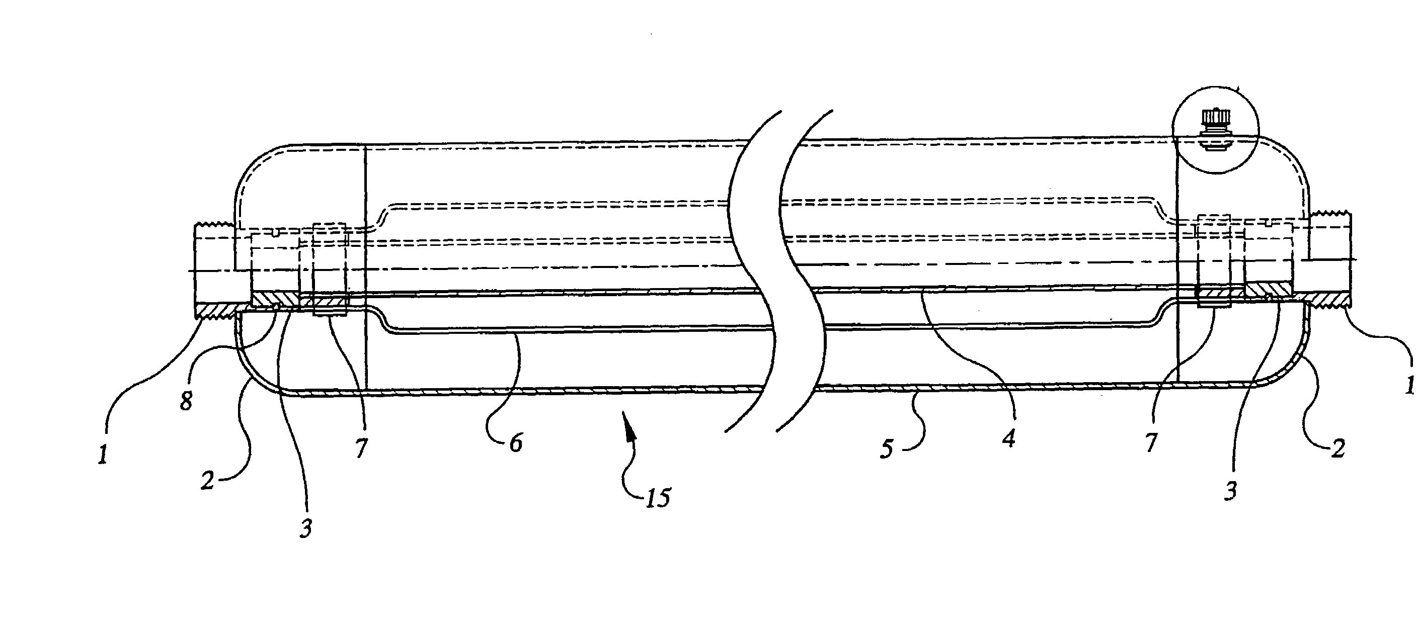
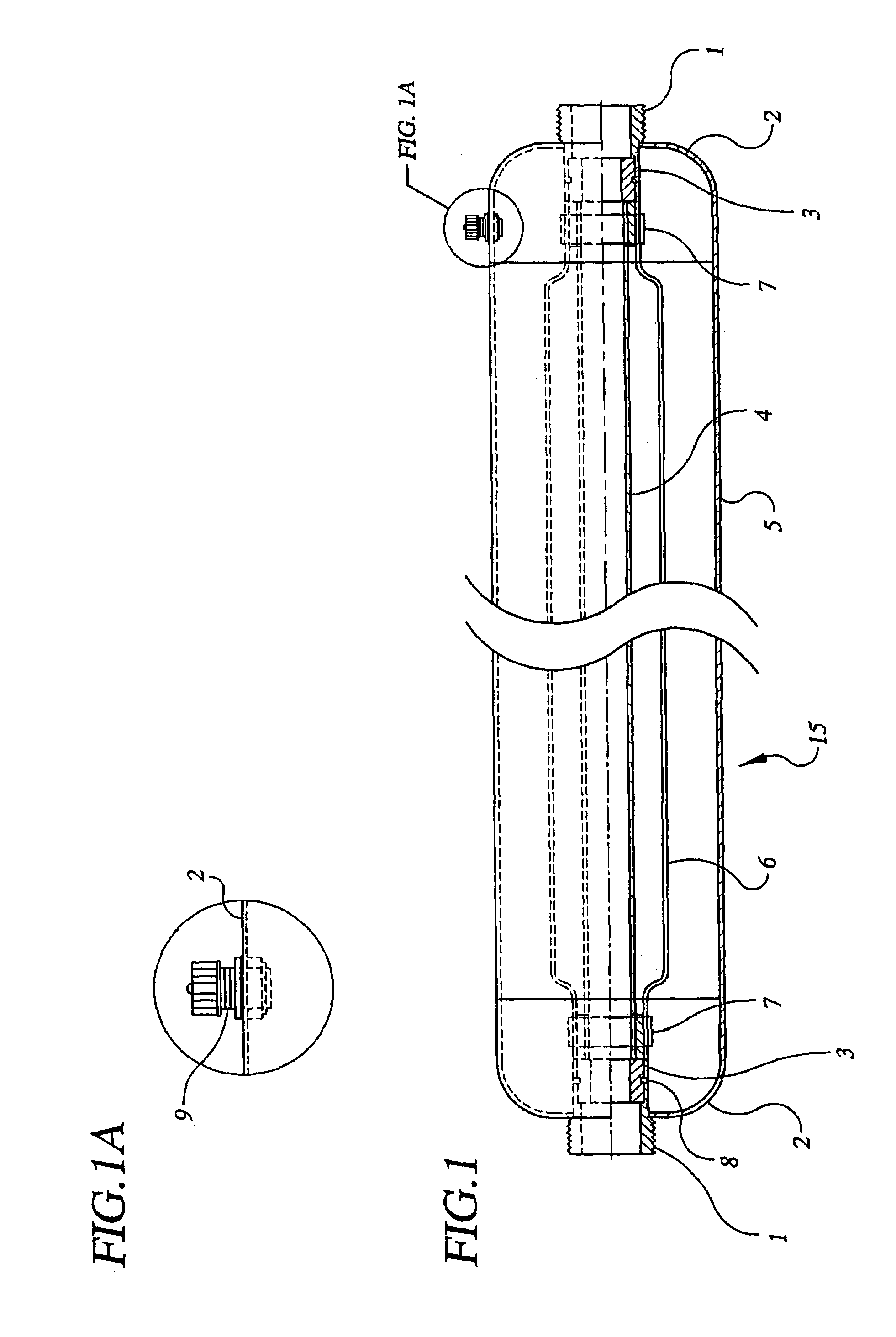
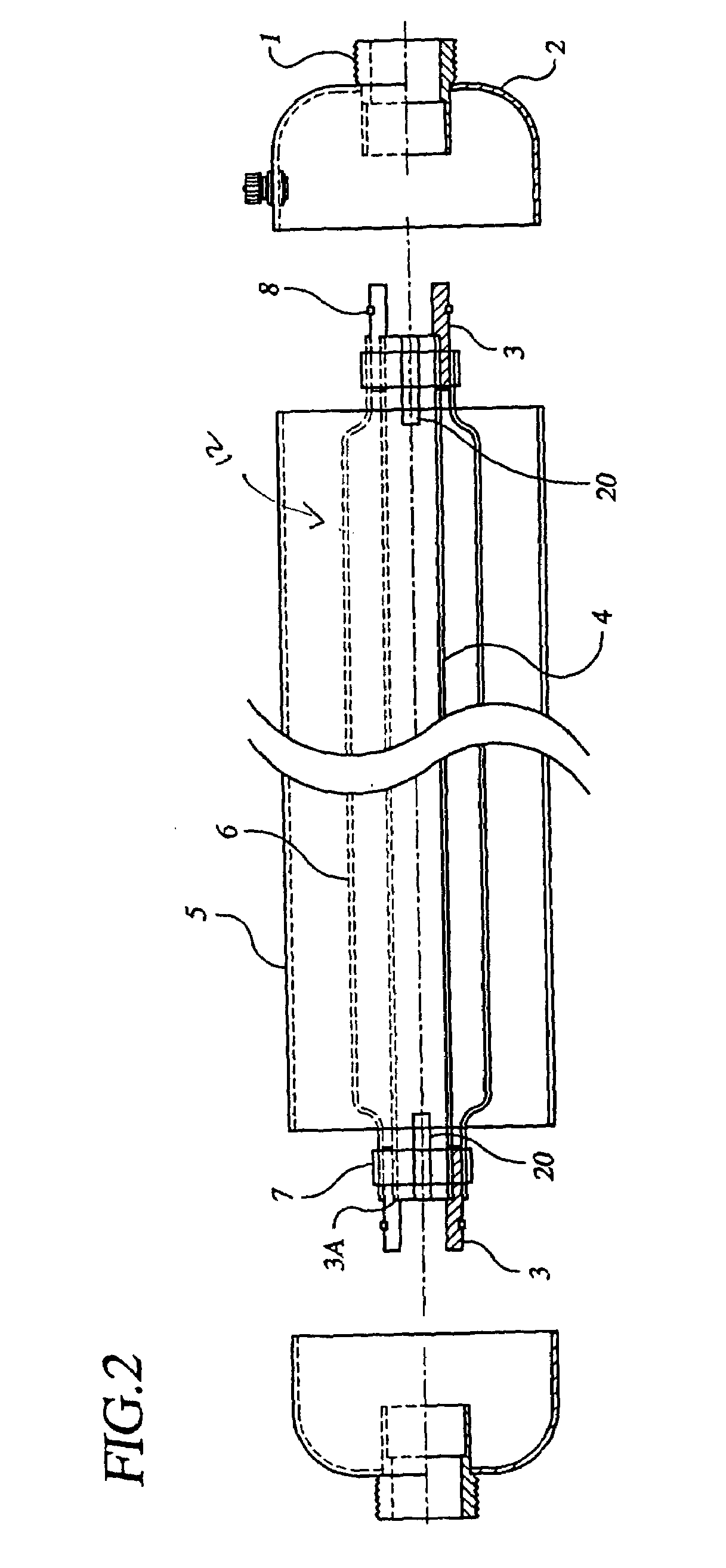
[0029]The diaphragm tank 10 is inserted in well casing 44, downstream of pump 46 (FIG. 6). The tank satisfies small demands from a downstream user without engaging the pump. When the pump is on, water flows through both tube 4 and the space between tube 4 and diaphragm 6. Water flows from one end of the space to the other, ensuring that water enters and leaves the tank on a first-in-first-out basis. Typical tank systems for in-well systems have capacities between 1.5 and 5 gal, for example, 1.5, 3.1 and 4.5 gal. The primary limitation on the size of the tank is the diameter of the well; however, the volume may be increased by lengthening the tank 10.
[0030]To prevent pressure spikes in the tank, the rate at which the diaphragm expands should be controlled. One method of accomplishing this is to use a variable speed pump. The speed of the pump increases gradually, slowing increasing the flow and the pressure of water within the tank. Another method is to install a pressure...
example 3
Anti-Hammer
[0034]The tank may also be used to reduce knocking, or hammering, in water systems that also contain air. For example, a water tower includes a drop pipe that occasionally requires emptying and clearing. When the pipe is refilled from the elevated tank, the falling water rapidly compresses the column of air in the pipe. The pressure from the falling water, which is accelerating under the force of gravity, is greater than the pressure exerted once the pipe is full, and the compressed air re-expands against the water. This expansion results in knocking in the pipes. Besides being noisy, it also strains pipe material, possibly weakening the pipe.
[0035]Indeed, in any large pipeline with water, the velocity of the water is great enough that potential energy from compression of air trapped within the line will cause hammering. A pressure tank can absorb the potential energy to prevent hammers. As for the water tower, the excess pressure at the point of the hammer strains the pi...
PUM
 Abstract
Description
Claims
Application Information
 - R&D
- Intellectual Property
- Life Sciences
- Materials
- Tech Scout
- Unparalleled Data Quality
- Higher Quality Content
- 60% Fewer Hallucinations
Browse by: Latest US Patents, China's latest patents, Technical Efficacy Thesaurus, Application Domain, Technology Topic, Popular Technical Reports.
© 2025 PatSnap. All rights reserved.Legal|Privacy policy|Modern Slavery Act Transparency Statement|Sitemap|About US| Contact US: help@patsnap.com


