Terminal block assembly for a hermetic compressor

Inactive Publication Date: 2006-09-19
TECUMSEH PROD CO
View PDF21 Cites 18 Cited by
  • Summary
  • Abstract
  • Description
  • Claims
  • Application Information

AI Technical Summary

Benefits of technology

[0008]The present invention provides a terminal assembly having a thick metallic disk that includes first diameter portion, which fits within an aperture of a compressor housing, and a second diameter portion, which abuts the housing wall. The metallic disk includes a plurality of holes each having a threaded surface which threadedly engages a threaded collar of a pin assembly to secure the pin assembly within th

Problems solved by technology

However, the cup-shaped terminal body of prior terminal assemblies are often unable to withstand the high heat of welding or brazing.
Consequently, the subsequent welding of the pre-assembled terminal assembly to the housing often results in damage to the terminal body, insulators and/or the conductive pins.
In addition, the interior of compressors using carbon dioxide as a working fluid reaches substantially high temperatures and pressures.
Prior term

Method used


Image

  • Terminal block assembly for a hermetic compressor
  • Terminal block assembly for a hermetic compressor
  • Terminal block assembly for a hermetic compressor

Examples


Example

[0042]The embodiments disclosed herein are not intended to be exhaustive or limit the invention to the precise forms disclosed in the following description. Rather the embodiments are chosen and described so that others skilled in the art may utilize its teachings.

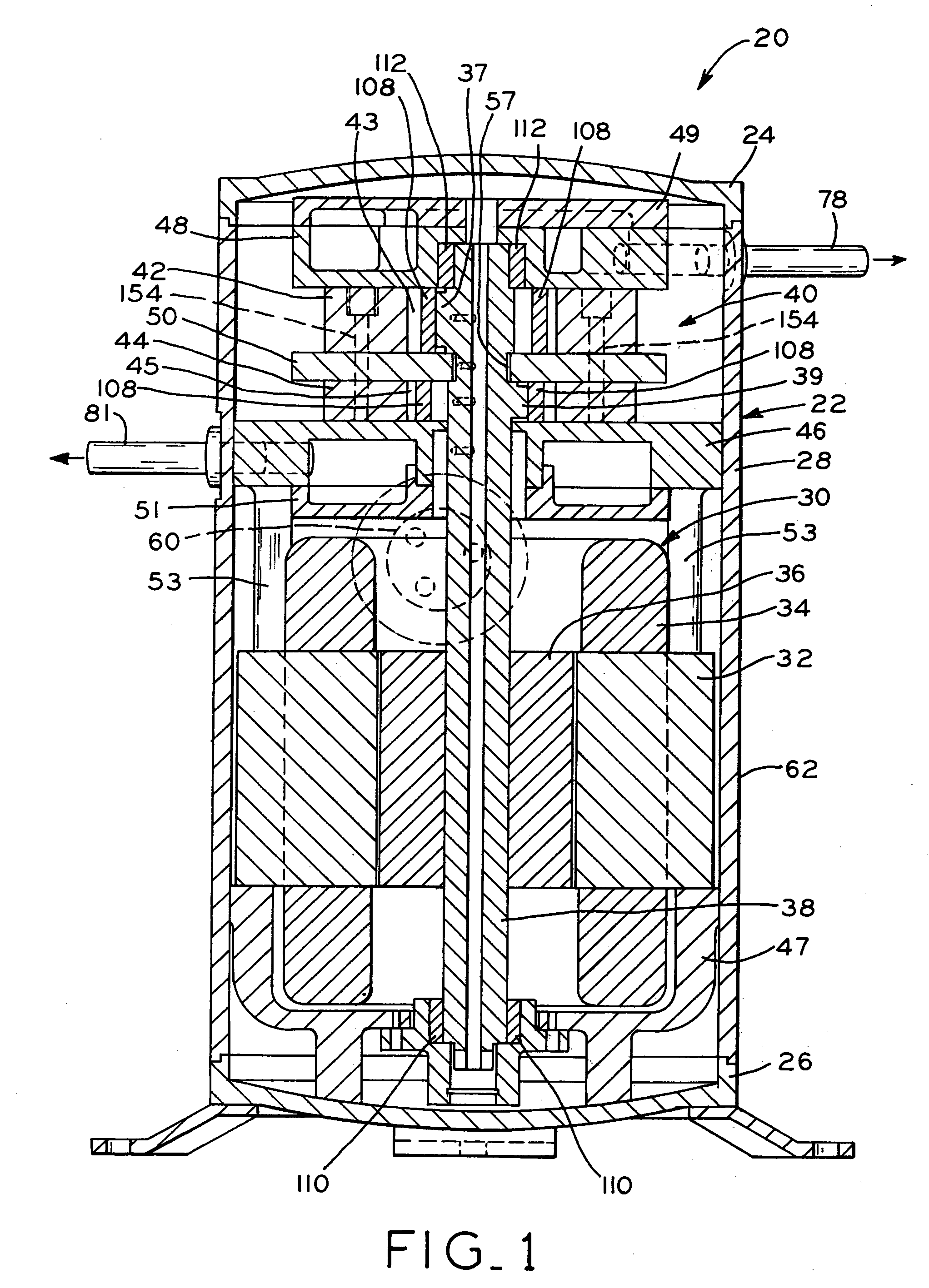
[0043]Referring to FIG. 1, hermetic compressor 20 comprises housing 22 which includes upper housing 24, lower housing 26, and cylindrical main housing 28. As better illustrated in FIG. 16, aperture 64 is defined in wall 62 of main housing 28. Returning now to FIG. 1, housing portions 24, 26 and 28 are formed of sheet steel and hermetically sealed by a method such as welding, brazing, or the like. Alternatively, either upper housing 24 or lower housing 26 may be integrally-formed with main housing 28. Disposed within housing 22 is motor 30 and compression mechanism 40. Motor 30 includes rotor 36, which is surrounded by stator 32 and fixed to crankshaft 38. Stator 32 includes windings 34, which are connected by lead wires (n...


PUM


Abstract

A terminal assembly for a hermetic compressor including a metallic disk having an interior side, an opposite exterior side, and a plurality of holes extending therethrough, the interior side of the metallic disk defining a first diameter sized to fit within an aperture of a compressor housing, the metallic disk defining a second diameter adjacent the first diameter and sized larger than the first diameter; and a plurality of terminal pin assemblies, each one of the terminal pin assemblies received in a corresponding one of the plurality of holes. Each of the terminal pin assemblies include an elongate conductive pin; and an annular collar disposed about the conductive pin and having a threaded outer surface, wherein the threaded outer surface threadedly-engages a corresponding one of the threaded holes.

Description

BACKGROUND OF THE INVENTION[0001]1. Field of the Invention[0002]The present invention pertains to hermetically sealed, positive displacement compressors for use in refrigeration systems such as air conditioners, refrigerators and the like, and methods for assembling such compressors.[0003]2. Description of the Related Art[0004]Various types of positive displacement compressors have been used in refrigeration systems including, for example, reciprocating piston, rotary vane, and scroll type compressors. In addition, multi-cylinder compressors, such as twin cylinder rotary compressors, are also known in the art. In general, twin cylinder rotary compressors comprise a housing containing a motor and a compression mechanism. The compression mechanism includes two cylinders, each defining a bore. The motor generally includes a crankshaft that extends through the two cylinders and has two eccentric portions, one located in the bore of each cylinder. The crankshaft is driven by the rotor of...

Claims


Application Information

Patent Timeline
IPC IPC(8): F04B17/00F01C21/10F04B39/12F04C18/356F04C23/00F04C29/00H02K5/22
CPCF01C21/10F04B39/121F04C23/008H02K5/225F04C29/0085F04C18/3562Y10S417/902F04C2230/231F04C2230/60
Inventor YAP, ZER KAI
Owner TECUMSEH PROD CO
Why Eureka
Try Eureka