Tool changer of machine tool

a technology of machine tools and tool changers, which is applied in the direction of manufacturing tools, work transfer apparatus, protection and storage accessories, etc., can solve the problems of increasing the size and cost of the entire machine, and achieve the effect of efficient storage of long tools

Inactive Publication Date: 2006-09-19
DMG MORI CO LTD
View PDF22 Cites 20 Cited by
  • Summary
  • Abstract
  • Description
  • Claims
  • Application Information

AI Technical Summary

Benefits of technology

[0006]The present invention was devised in view of the above-described conventional situation and it is an object of the present invention to provide a tool changer of a machine tool capable of suppressing cost increase and preventing size increase of the machine in mounting a tool magazine.
[0018]In the above-described embodiment, the tool is held to be directed in the direction crossing the radial direction. Therefore, a vacant space can be utilized to efficiently house a long tool.

Problems solved by technology

Both of the above-described conventional tool changers, however, require a specialized actuator for moving the support table and the tool holder, and further require separately secured space for placing the large support table and gate-shaped frame on the bed.
This poses a problem of cost increase and size increase of the entire machine.

Method used


Image

  • Tool changer of machine tool
  • Tool changer of machine tool
  • Tool changer of machine tool

Examples


Embodiment Construction

[0030]Hereinafter, an embodiment of the present invention will be described based on the attached drawings.

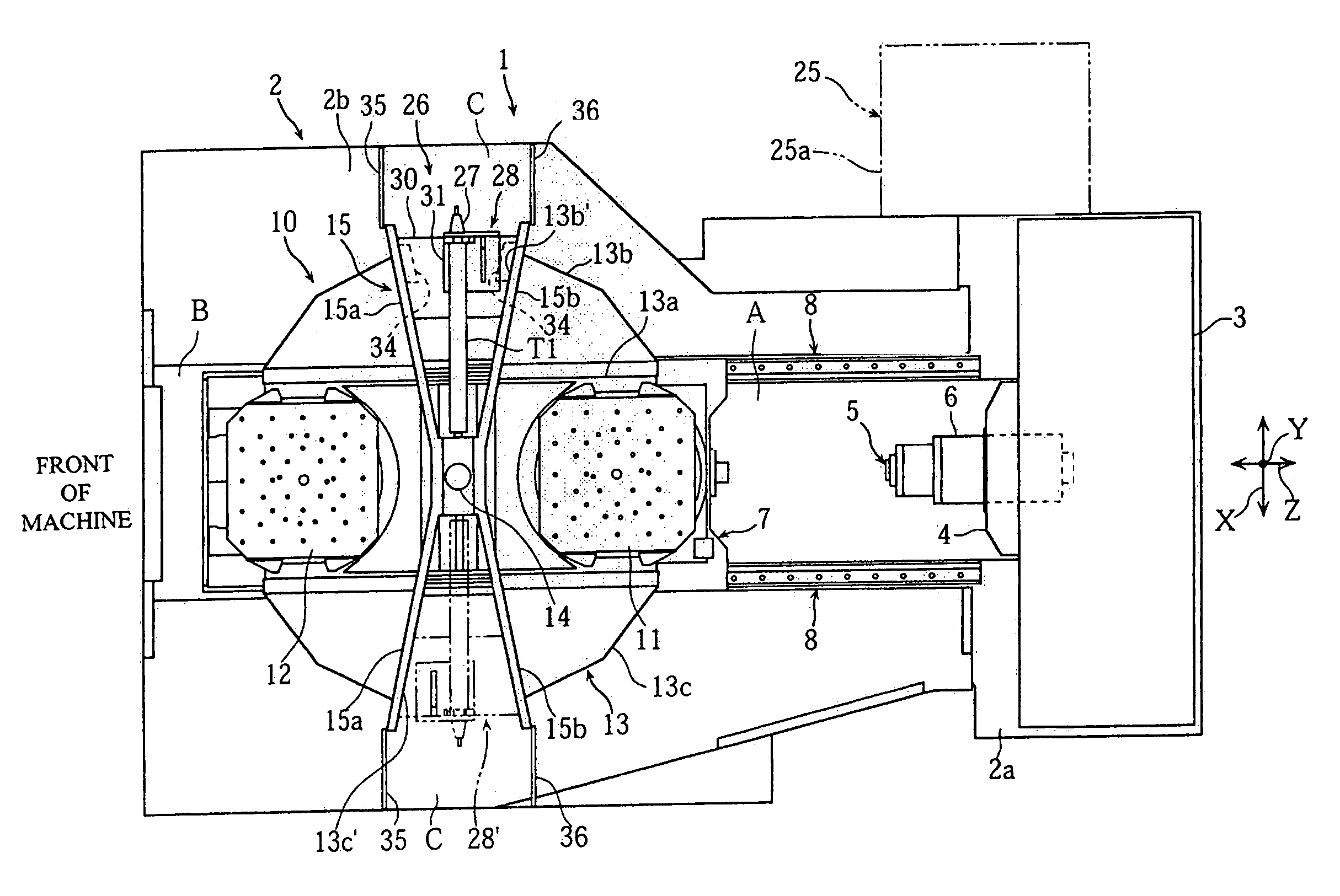
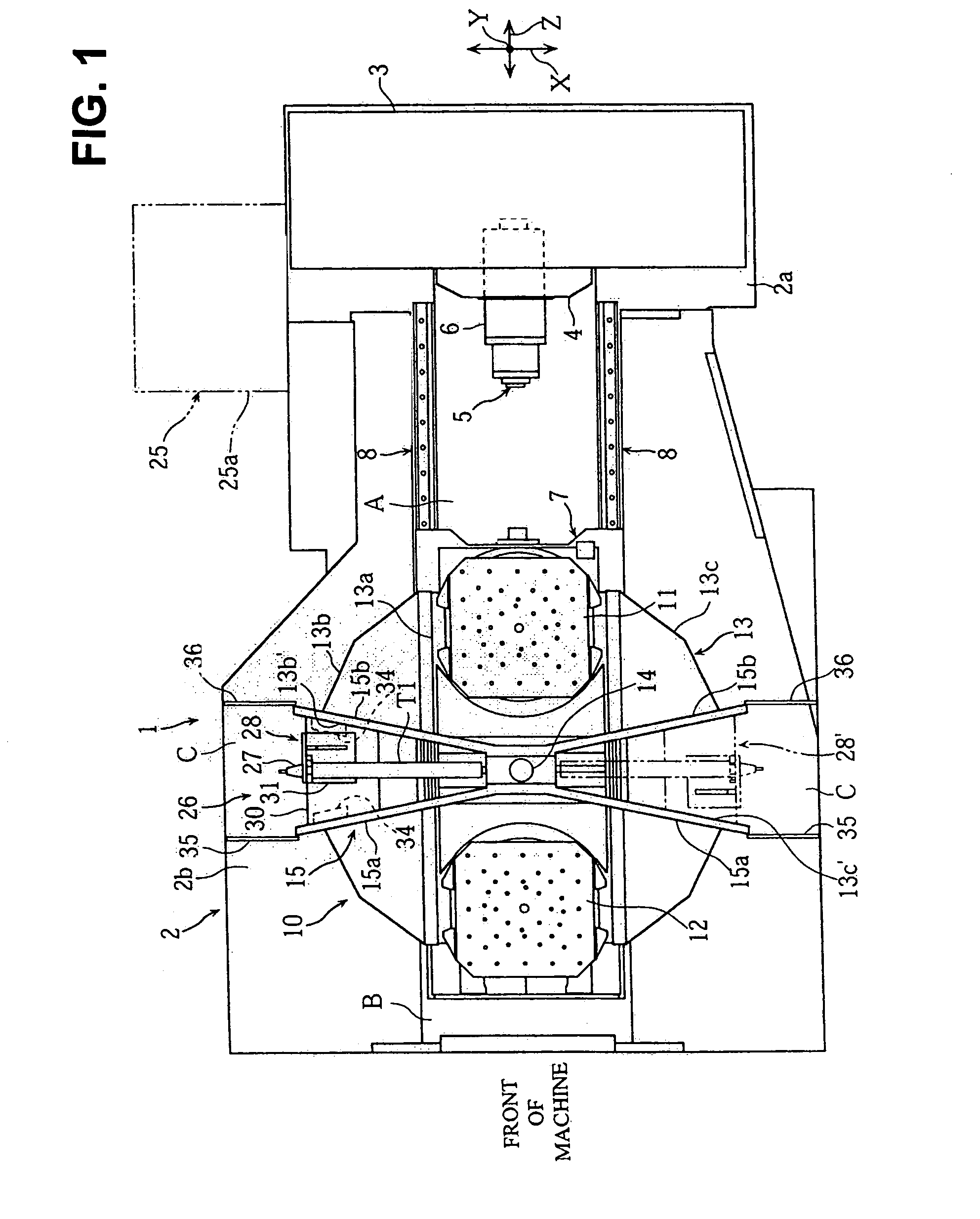
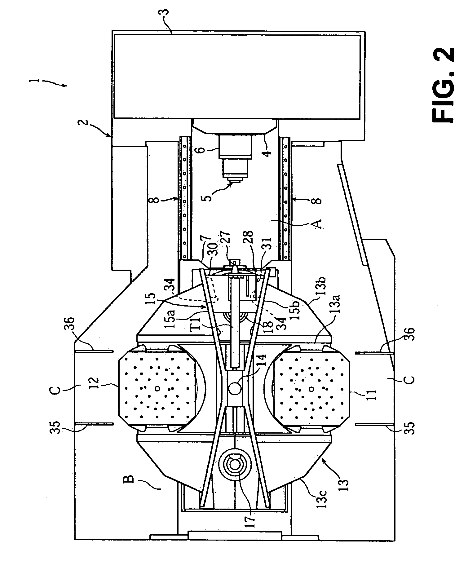
[0031]FIG. 1 to FIG. 11 are views to explain a tool changer of a horizontal machining center (machine tool) according to an embodiment of the present invention. FIG. 1 is a plan view of the horizontal machining center, FIG. 2 to FIG. 6 are plan views showing tool changing operations of the tool changer, FIG. 7 and FIG. 8 are a side view and a perspective view of the horizontal machining center, FIG. 9(a) and FIG. 9(b) are perspective views of the tool magazine, FIG. 10 is a perspective view of a tool holding mechanism and a tool holder, and FIG. 11 is a cross-sectional view of a clamp mechanism of a pallet changer.

[0032]In the drawings, 1 denotes the horizontal machining center. The horizontal machining center 1, when seen from a front side of the machine, is structured such that a substantially rectangular parallelepiped column 3 is fixedly disposed on a back end portion 2a of...


PUM

PropertyMeasurementUnit
diameteraaaaaaaaaa
distanceaaaaaaaaaa
sizeaaaaaaaaaa

Abstract

The present invention provides a tool changer of a machine tool capable of suppressing cost increase and preventing size increase of the machine when a tool magazine is mounted. In a tool changer of a machine tool provided with a pallet change mechanism 10 in which a machining-side pallet 11 disposed on a machining area A side and a standby-side pallet 12 disposed on a standby area B side are turned around a turn shaft 14 by a turning member 13 to be automatically changed, a tool magazine 28 holding a plurality of tools T1 to T4 is disposed between the machining-side pallet 11 and the standby-side pallet 12 in the turning member 13 and the tool magazine 28 is turned by the turning member 13 so that the tools T1 to T4 face a spindle 5 disposed on the machining area A side.

Description

BACKGROUND OF THE INVENTION[0001]1. Field of the Invention[0002]The present invention relates to a tool changer of a machine tool provided with a pallet change mechanism in which a machining-side pallet and a standby-side pallet are turned by a turning member around a turn shaft to be automatically changed.[0003]2. Description of the Related Art[0004]For example, a horizontal machining center sometimes uses, for machining a workpiece, a long tool that is longer than a standard size tool. As an example of a tool changer capable of automatically changing such long tools, there is a tool changer structured such that a support table on which a plurality of long tools are arranged is moved by an actuator between a standby position and a tool change position on a bed, thereby allowing a spindle to grip a required tool (for example, Japanese Utility Model Registration No. 2532663). As another example, there is a tool changer structured such that a gate-shaped frame is installed on a bed an...

Claims


Application Information

Patent Timeline
Patent Type & Authority Patents(United States)
IPC IPC(8): B23Q3/157B23Q1/66B23Q3/155B23Q7/00
CPCB23Q1/66B23Q3/15526B23Q3/15706Y10T483/179Y10T409/30392Y10T483/16Y10T483/115Y10T29/5196B23Q3/15536
Inventor NAKAZAWA, SHUNSUKEKANEDA, NOBUHIROYASUMURA, RYOSUKE
Owner DMG MORI CO LTD
Why Eureka
Try Eureka