Rocking operation type electric component

a technology of electric components and operation types, which is applied in the direction of electrical switches, contact mechanisms, electrical apparatus, etc., can solve the problems of insufficient mechanical strength, liquid leaking into the case through the gap between the installation holes and the shafts, and the operation reliability of the rocking operation type electric component can be degraded

Active Publication Date: 2006-09-19
ALPS ALPINE CO LTD
View PDF8 Cites 8 Cited by
  • Summary
  • Abstract
  • Description
  • Claims
  • Application Information

AI Technical Summary

Benefits of technology

[0010]Accordingly, the invention has been made to solve the above-mentioned problems, and it is an object to a rocking operation type electric component which can prevent ingress of liquid, secure a mechanical strength of an operation knob, and provide an aesthetic outer appearance.
[0012]Due to the fact that the mounting frame which is protrusively formed on the case has the pair of through-holes and the rotation shafts of the operation knob are respectively snap-fitted into the through-holes from the outside of the mounting frame, the operation knob which is rotatably supported by the mounting frame can cover the mounting frame, and the rotation shafts and the through-holes are not exposed to the outside. Therefore, when liquid such as rain water or beverage adheres to the case or the operation knob, the possibility of the liquid to leak into the case is significantly reduced. In addition, a short circuit or corrosion of the signal generating unit due to ingress of the liquid can be prevented, whereby operational reliability of the rocking operation type electric component can be ensured. Also, since the rotation shafts formed on the operation knob are fitted into the through-holes formed in the case which has a greater strength than the operation knob, when compared with a mounting structure in which shafts formed on a case are fitted into holes defined in an operation knob, it is easy to secure a mechanical strength of the operation knob. Moreover, since the rotation shafts of the operation knob and the through-holes of the mounting frame are not exposed to the outside, an aesthetic outer appearance of the rocking operation type electric component can be provided.
[0013]In the above construction, it can be envisaged that two mounting frames, which are located in parallel with surfaces having the through-holes adjacent each other, and a partition wall, which is located between the two mounting frames, are protrusively formed on the case; and, at an opened end of the operation knob, a side wall facing the partition wall has a tapered portion that a front end portion gradually decreases in its thickness and a gap between the partition wall and the front end portion of the side wall of the operation knob gradually decreases. Therefore, when an unintentional force is applied to the operation knob such as when an elbow of an operator comes into contact with the operation knob, due to the presence of the partition wall, mis-operation of the operation knob can be prevented, whereby safety can be improved. Further, even when a gap between operation knobs which are installed parallel to each other is decreased, due to the presence of the partition wall, it is possible to clearly distinguish the respective operation knobs through a finger's touch. Therefore, a rocking operation type electric component which can be appropriately applied to a power window mechanism for a vehicle can be obtained. Meanwhile, when snap-fitting the operation knob into the mounting frame, the side walls of the operation knob which have the rotation shafts are elastically bent outward. In this regard, since the side wall of the operation knob which faces the partition wall is formed with the tapered portion and this tapered portion does not substantially increase the widthwise size of the operation knob even when the corresponding side wall is bent outward during installation of the operation knob, the gap between the partition wall and the side wall of the operation knob which faces the partition wall can be remarkably decreased, whereby it is possible to simply and reliably install the operation knob on the mounting frame and accomplish miniaturization of the entire electric component.

Problems solved by technology

In this regard, because a signal generating unit including contact portions is arranged inside the case, if the liquid leaking into the case from the outside adheres to the signal generating unit, a short circuit or corrosion of the signal generating unit can be caused, and operational reliability of the rocking operation type electric component can be degraded.
However, due to the fact that the installation holes of the operation knob into which the shafts of the case are snap-fitted are exposed to the outside, the possibility of liquid to leak into the case through the gap between the installation holes and the shafts still exists.
Also, because it is the norm that the operation knob has a strength which is no greater than that of the case, when adopting the structure in which the shafts of the case are snap-fitted into the installation holes of the operation knob, a mechanical strength is insufficient around the installation holes of the operation knob, and therefore, the operation knob is likely to be broken around the installation holes.
Moreover, even in this conventional example, since the installation holes of the operation knob and the shafts of the case are viewed from the outside, the design or the outer appearance of the rocking operation type electric component is deteriorated.

Method used


Image

  • Rocking operation type electric component
  • Rocking operation type electric component
  • Rocking operation type electric component

Examples


Embodiment Construction

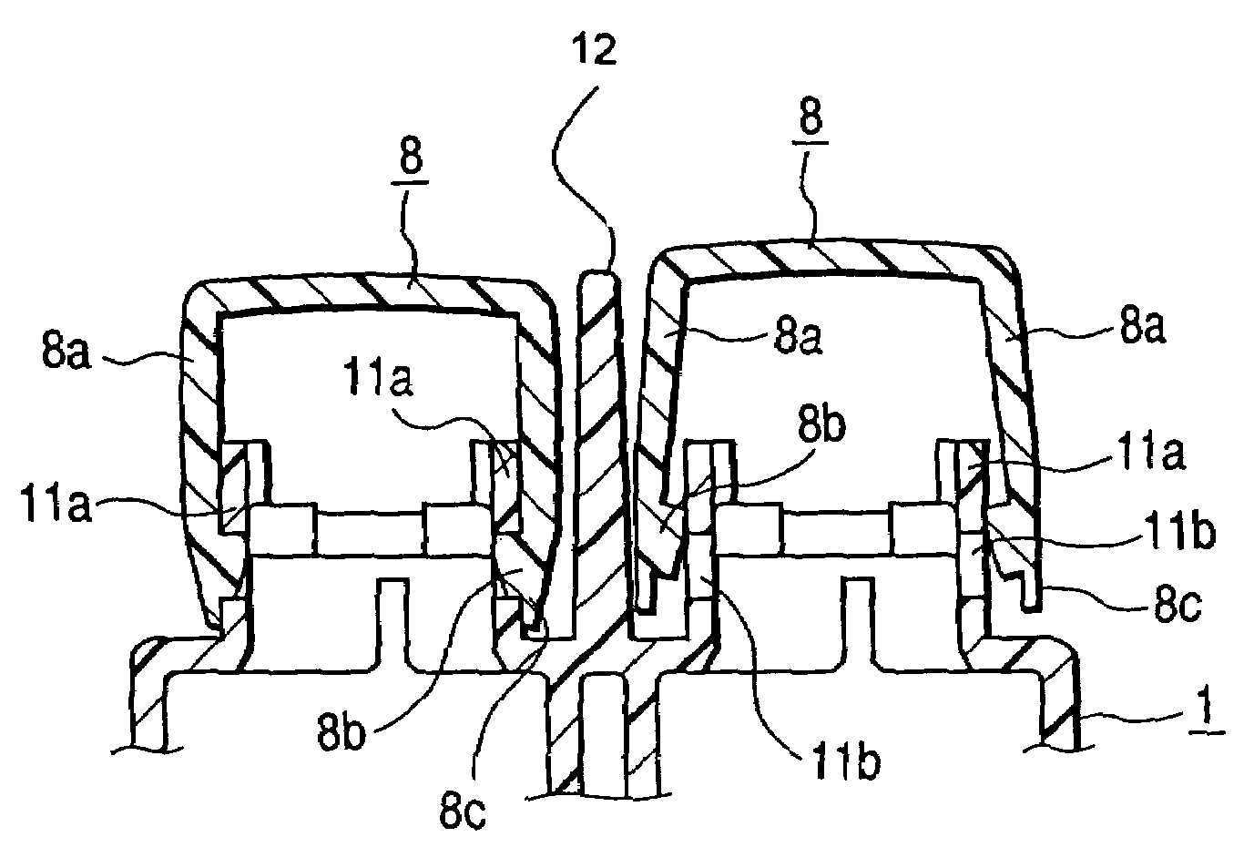
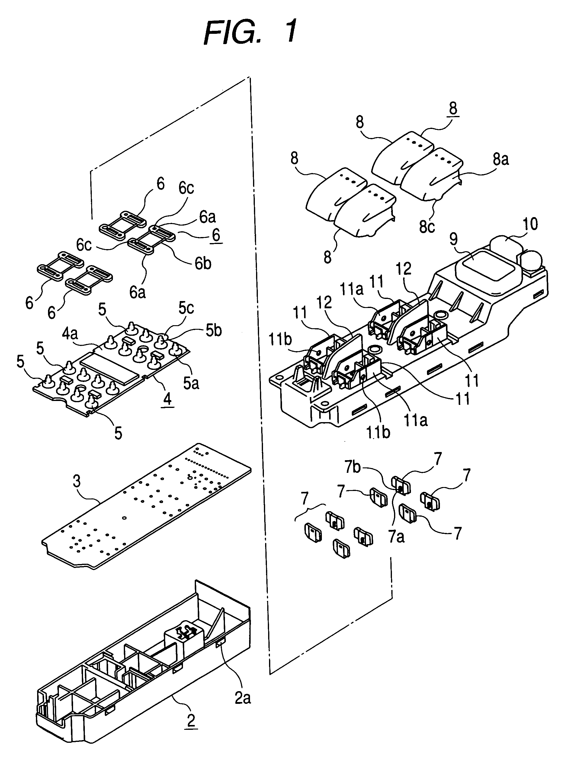
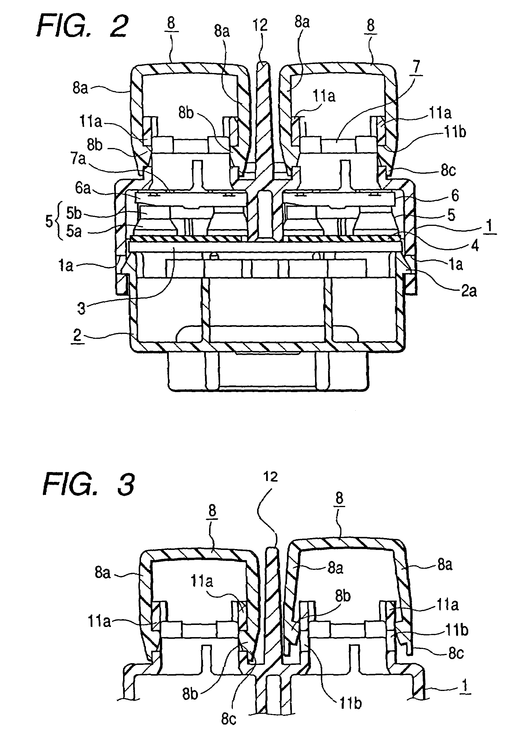
[0020]Hereafter, a preferred embodiment of the present invention will be described with reference to the accompanying drawings. FIG. 1 is an exploded perspective view illustrating a switch device according to an embodiment of the present invention, FIG. 2 is a cross-sectional view of the switch device shown in FIG. 1, FIG. 3 is an explanatory view illustrating an assembling process for installing an operation knob of the switch device, and FIG. 4 is an explanatory view illustrating a structure of contact portions of the switch device.

[0021]A switch device according to the present embodiment is applied to an operation switch of a power window mechanism for a vehicle. The switch device mainly includes an upper case 1 and a lower case 2 which constitutes a casing, a circuit board 3 which is disposed in the casing, a click rubber 4 which is mounted on the circuit board 3 and has a plurality of hollow protrusions 5, cam members 6 which are placed on the plurality of hollow protrusions 5 ...


PUM


Abstract

A rocking operation type electric component is presented that includes: an operation knob that has a bottomed case-shaped configuration and is rockably held; a signal generating unit that includes a movable element pressed and driven by the operation knob and generates a different electric signal in response to a position change of the movable element; and a case on which a mounting frame for pivotally supporting the operation knob is protrusively provided formed and in which the signal generating unit is received. A pair of rotation shafts which face each other are protrusively formed on inner wall portions of the operation knob, respectively. Through-holes are respectively formed in a pair of wall portions of the mounting frame which face each other. The rotation shafts are fitted into the through-holes from the outside of the mounting frame to be rotatably supported by the mounting frame.

Description

[0001]This application claims the benefit of priority to Japanese Patent Application No. 2004-267210, filed on Sep. 14, 2004, herein incorporated by reference.BACKGROUND OF THE INVENTION[0002]1. Field of the Invention[0003]The present invention relates to a rocking operation type electric component, such as a switch device, a variable resistor and the like, in which an operation knob is rocked (seesawed), and more particularly, to a mounting structure of the operation knob.[0004]2. Description of the Related Art[0005]Generally, a rocking operation type electric component, which serves, for example, as a switch device applied to a power window mechanism for a vehicle, includes an operation knob which can be rocked and has a bottomed case-shaped configuration, a signal generating unit which includes a movable element to be pressed and driven by the operation knob and generates a different electric signal in response to a position change of the movable element, and a case which receive...

Claims


Application Information

Patent Timeline
Patent Type & Authority Patents(United States)
IPC IPC(8): H01H9/00
CPCH01H21/22H01H2233/074H01H2021/225
Inventor GALVIN, MICHAELITO, CHIEKO
Owner ALPS ALPINE CO LTD
Why Eureka
Try Eureka