Composite piezoelectric apparatus and method

a piezoelectric apparatus and piezoelectric technology, applied in the field of ultrasonic transducers, can solve the problems of large coupling loss, limited energy transfer efficiency, expensive and laborious task,

Active Publication Date: 2006-09-19
SONAVATION INC
View PDF53 Cites 79 Cited by
  • Summary
  • Abstract
  • Description
  • Claims
  • Application Information

AI Technical Summary

Benefits of technology

[0010]The present invention relates to composite piezoelectric apparatus, transducers and methods of manufacture. In an embodiment, a composite piezoelectric apparatus has a sacrificial base and pillar array. The sacrificial base has a first composite piezoelectric material. The first composite piezoelectric material has a first volume percent of first piezoelectric material. The pillar array has a plurality of pillars. Each pillar has a second composite piezoelectric material. The second composite piezoelectric material has a second volume percent of second piezoelectric material. The first volume percent is lower than the second volume percent. In this way, the sacrificial base can be easily removed from the pillar array after the base and pillar array are sintered in the manufacture of a final composite piezoelectric transducer.
[0012]In further embodiments, a method of manufacturing a composite piezoelectric transducer from a sacrificial base and pillar array and a composite piezoelectric transducer made by the method are provided. The method includes molding the sacrificial base and the pillar array with first and second slips, respectively. The first slip has a first composite piezoelectric material with a first volume percent of first piezoelectric material. The second slip having a second composite piezoelectric material, said second composite piezoelectric material having a second volume percent of second piezoelectric material, wherein said first volume percent is lower than said second volume percent, whereby, said sacrificial base can be easily removed from the pillar array after the molded base and pillar array are sintered in the manufacture of the composite piezoelectric transducer.

Problems solved by technology

a) Firstly, the overall density of the composite is less that pure ceramic which in the case of PZT is approximately 8. This density and mechanical modulus gives rise, to an acoustic index of ˜30 megarayls (Mrayls). Most uses for transducers are either in medical or sonar applications where the medium of tissue or water has an acoustic index of about 1.5 Mrayls. This mismatch causes large coupling losses at the interface of the transducer and the material. A mechanical transformer in the form of matching layers of ¼ wavelength thickness of material with intermediate acoustic densities then needs to be inserted between the transducer and the material. The efficiency of energy transfer is thus limited to the affectivity of this mechanical transformer, which is compromised by the lack of materials available with acoustic indexes of about 6–20 Mrayls. By using a composite made up of a mixture of polymer and ceramic, a composite transducer can have an acoustic index of about 4–10 Mrayls depending on the percentage of ceramic in the transducer. This is much easier to couple to the target mediums and higher coupling efficiencies are achieved.
b) Secondly, under the stress of an electrical field a piezoelectric material (“piezo material”) will change its shape. This will cause internal stresses which hold the material in its solid form. If the piezo material is in the form of long, thin pillars, then the forces opposing the lengthening of the pillar will be the force of thinning the pillar that allows material to become part of the length extension. In a solid mass of ceramic this sideways resistance is substantial and only small displacements are possible. If the pillar is held in a polymer, then this resistance to thinning is minimal allowing the pillar to extend its length at a greater efficiency.
This is an expensive and laborious task with quality and yield difficulties.

Method used


Image

  • Composite piezoelectric apparatus and method
  • Composite piezoelectric apparatus and method
  • Composite piezoelectric apparatus and method

Examples


Embodiment Construction

[0019]While the present invention is described herein with reference to illustrative embodiments for particular applications, it should be understood that the invention is not limited thereto. Those skilled in the art with access to the teachings provided herein will recognize additional modifications, applications, and embodiments within the scope thereof and additional fields in which the invention would be of significant utility.

[0020]In embodiments, the present invention relates to composite piezoelectric apparatus, transducers and methods of manufacture.

Different Composite Material Volume Percents

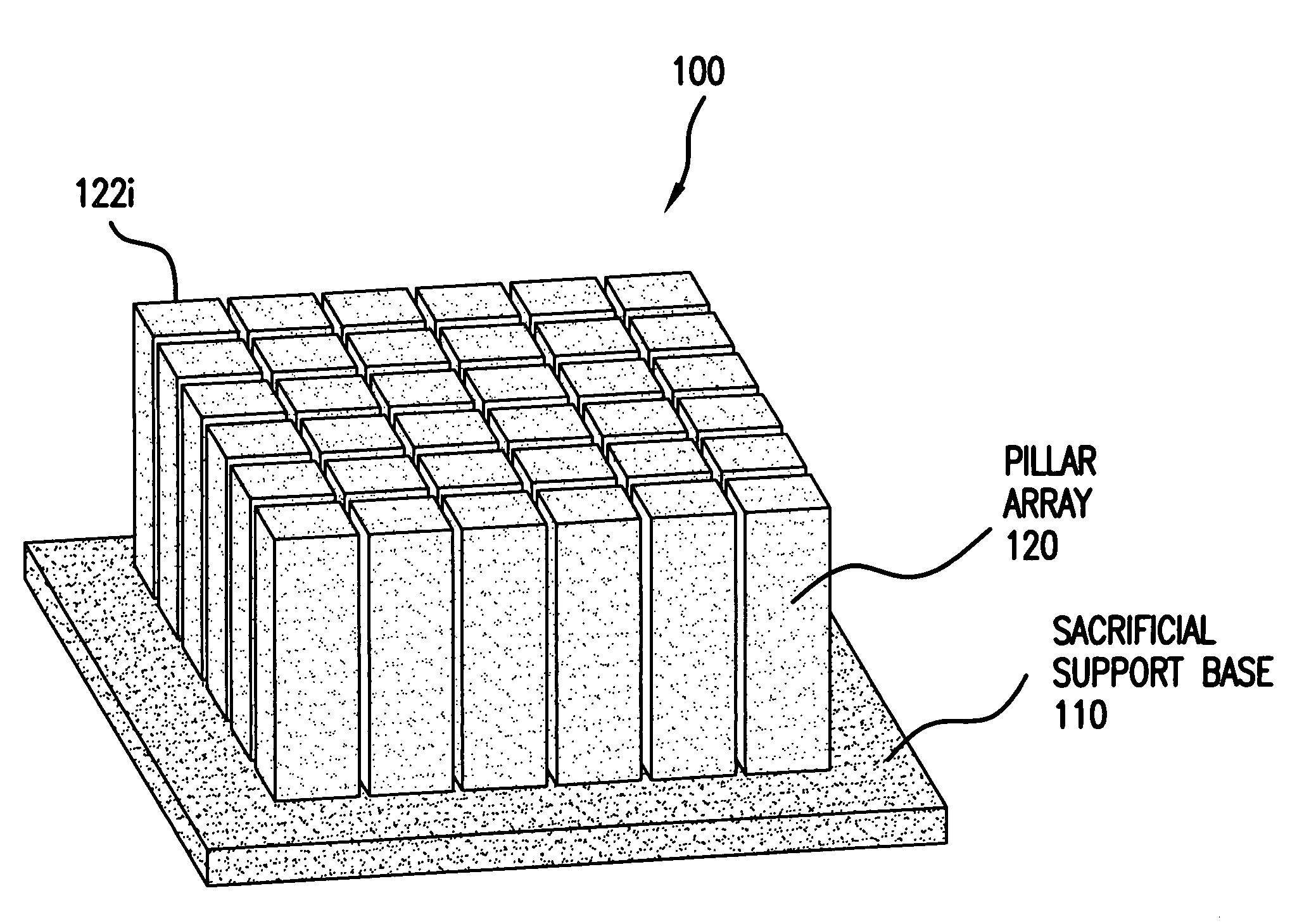
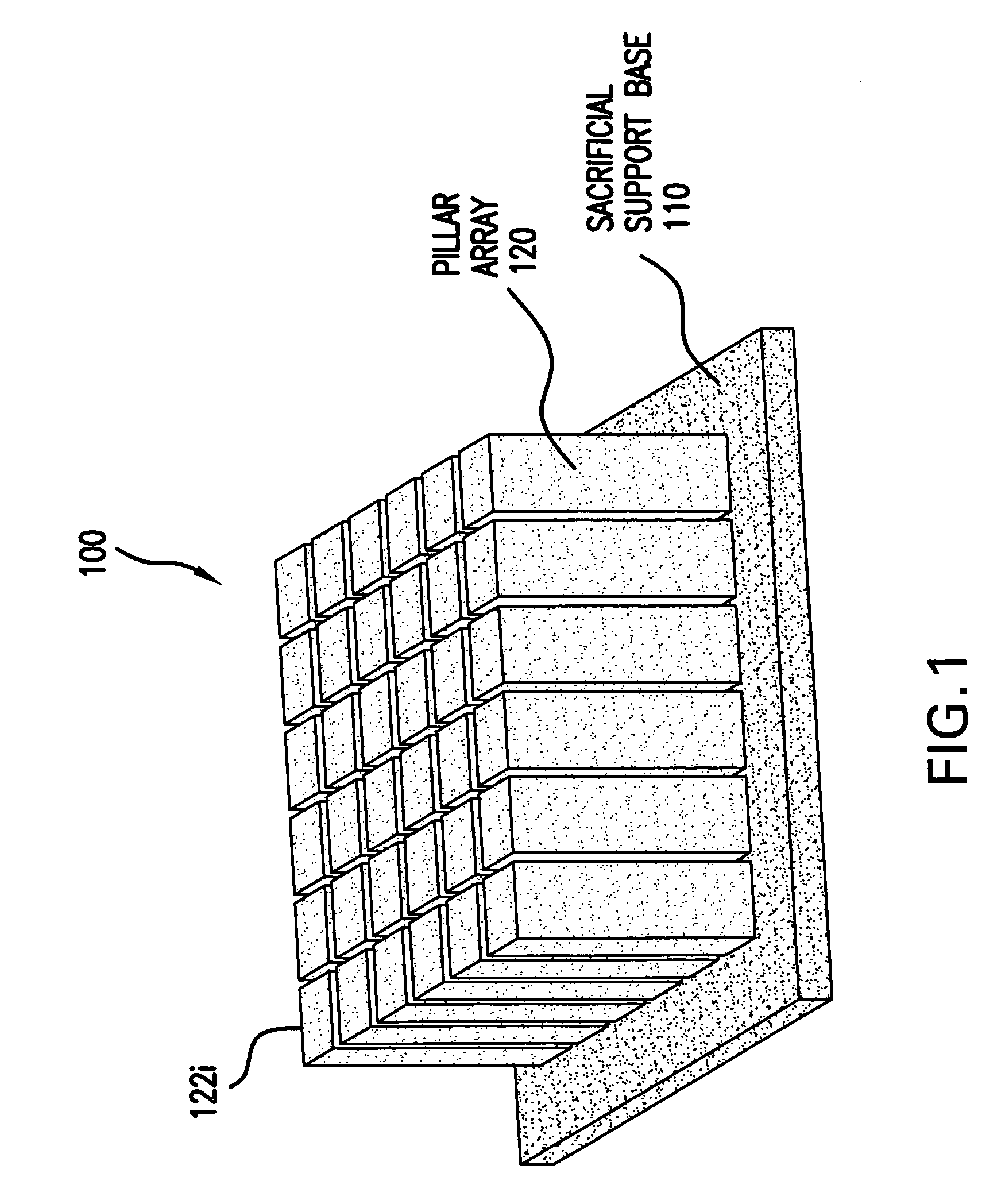
[0021]FIG. 1 is a diagram of a composite piezoelectric apparatus 100 having a sacrificial base 110 and pillar array 120 according to an embodiment of the present invention. Sacrificial base 110 has a composite piezoelectric material made up of piezoelectric material at a first volume percent. Likewise, pillar array 120 is made up of a number of pillars 122i. Only a 6×6 array of 36 pill...


PUM

PropertyMeasurementUnit
volume percentaaaaaaaaaa

Abstract

The present invention relates to composite piezoelectric apparatus, transducers and methods of manufacture. In an embodiment, a composite piezoelectric apparatus has a sacrificial base and pillar array. Different volume percents of piezoelectric material are used in the sacrificial base and pillar array. A first volume percent in the base is lower than the second volume percent in the pillar array. In this way, the sacrificial base can be easily removed from the pillar array after the base and pillar array are sintered in the manufacture of a final composite piezoelectric transducer. A method of manufacturing a composite piezoelectric transducer from a sacrificial base and pillar array and a composite piezoelectric transducer made by the method are provided. A composite piezoelectric transducer stack is provided.

Description

[0001]This application claims the benefit of U.S. Provisional Appl. No. 60 / 525,927, filed Nov. 29, 2003 (incorporated in its entirety herein by reference for all purposes).BACKGROUND OF THE INVENTION[0002]1. Field of the Invention[0003]The present invention relates generally to ultrasonic transducers and their fabrication.[0004]2. Related Art[0005]Composite piezoelectric transducers are devices that comprise part sintered, densified ceramic (for example, lead zirconate titanate (PZT)) embedded in a polymer. The composite structure enhances the efficiency of electrical to mechanical energy conversion and propagation, and in reverse, mechanical to electrical energy conversion. The geometry of the structure can have many forms. One example geometry is a 1–3 composite. This 1–3 refers to a material where the electrical field is applied through the thickness of a plate and the mechanical motion is also in this direction.[0006]The composite structure derives performance improvements in tw...

Claims


Application Information

Patent Timeline
Patent Type & Authority Patents(United States)
IPC IPC(8): H01L41/04H01L41/08B06B1/06H01L41/18H01L41/22
CPCB06B1/064H01L41/37H01L41/29H01L41/183Y10T29/42H01L41/1876B33Y80/00H10N30/852H10N30/8554H10N30/06H10N30/092
Inventor SCOTT, WALTER GUY
Owner SONAVATION INC
Why Eureka
Try Eureka