Method and apparatus for azimuthal resistivity measurements in a borehole

a technology of azimuthal resistivity and measurement method, which is applied in the field of interpretation of measurements made by well logging resistivity instruments, can solve the problems of poor longitudinal resolution, invading earth formations, and ineffective focusing, and achieve high-resolution resistivity effects

Active Publication Date: 2006-09-19
BAKER HUGHES INC
View PDF22 Cites 29 Cited by
  • Summary
  • Abstract
  • Description
  • Claims
  • Application Information

AI Technical Summary

Benefits of technology

[0014]The present invention includes a method of determining azimuthal resistivity of earth formations. One or more pad mounted sensors are arranged in a laterolog configuration. By measuring the currents in the various guard electrodes, the pad and a central electrode while monitoring the voltage difference between at least one pair of monitor electrodes, shallow and deep resistivity measurements may be obtained. In addition, a microelectrode on a pad may be used for a high resolution resistivity measurement.

Problems solved by technology

A drawback of the Scholberg device is that its longitudinal resolution is poor, being about one meter.
In addition, it is well known that by the time wireline logging devices are run in a borehole, there may be invasion of the earth formations by drilling mud from the borehole.
This suffers from the drawback that the focusing is not particularly effective.
In addition, the Threadgold device also has poor longitudinal resolution.
It is difficult and complicated to make such a sonde, which requires concentric rings of electrodes.
The devices disclosed in Seeman and in Smits are still susceptible to errors due to poor azimuthal focusing.
In the presence of a conducting mud (water based mud), focusing in the azimuthal direction becomes problematic.
This results in a reduced azimuthal resolution of the resistivity measurements.
The Evans '722 device does not provide a capability of providing different depths of investigation.

Method used


Image

  • Method and apparatus for azimuthal resistivity measurements in a borehole
  • Method and apparatus for azimuthal resistivity measurements in a borehole
  • Method and apparatus for azimuthal resistivity measurements in a borehole

Examples


Embodiment Construction

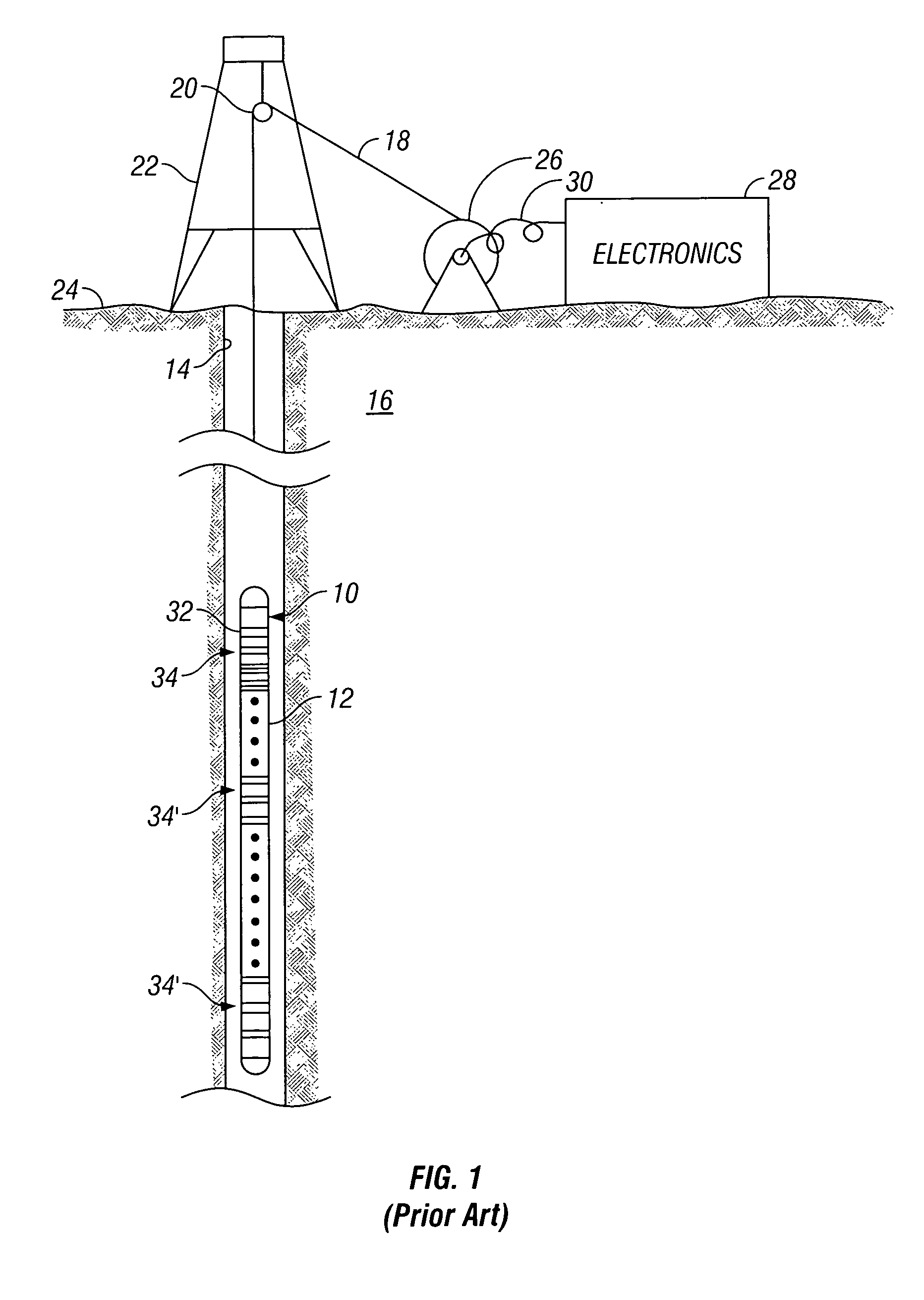
[0023]Referring now to FIG. 1, an exemplary prior art differential array resistivity instrument 10 will be described. Such an instrument has been described in U.S. Pat. No. 6,060,885 to Tabarovsky et al. having the same assignees as the present invention and the contents of which are incorporated herein by reference. The instrument 10 is shown disposed in a borehole 14 penetrating an earth formation 16 and supported by a wire cable 18. The cable 18 is supported and guided by a sheave wheel 20 suspended from a well structure 22 in place on the earth's surface 24 over the wellbore 14. The cable 18 is stored on a cable drum 26 which is controlled at the surface to lower and raise the differential array instrument 12 within the wellbore 14 at a predetermined logging speed. Commands for controlling the operation of the instrument 12 and the data collected by the instrument are transmitted electrically through the cable 18 and via interconnecting cable 30 to an electronics package 28 loca...


PUM


Abstract

An azimuthal resistivity logging tool includes one or more pads for making azimuthal resistivity measurements of earth formation. Current from the pads, guard electrodes and a measure electrode are measured while monitoring the voltage difference between pairs of monitor electrodes. The pads and an adjacent portion of the tool body form a guard electrode. In addition, microelectrodes are provided on the pads for obtaining high resolution resistivity measurements.

Description

BACKGROUND OF THE INVENTION[0001]1. Field of the Invention[0002]The invention is related generally to the field of interpretation of measurements made by well logging resistivity instruments for the purpose of determining the properties of earth formations. More specifically, the invention is related to an apparatus and method for determination of the electrical resistivity of an earth formation when there is an azimuthal variation in the resistivity.[0003]2. Background of the Art[0004]A well logging device with electrodes that has been commercially available for many years and that is known under the name “Dual Laterolog” is described in U.S. Pat. No. 3,772,589 to Scholberg. That device comprises an array of annular electrodes used for sending electrical measurement currents into the formations for the purpose of measuring their resistivity. The measurement currents are focused in an annular zone having the form of a disk perpendicular to the borehole axis by means of auxiliary cur...

Claims


Application Information

Patent Timeline
Patent Type & Authority Patents(United States)
IPC IPC(8): G01V3/18G01V3/26G01V3/10G01V3/20
CPCG01V3/20
Inventor FABRIS, ANTONIOKHOKHAR, RASHID
Owner BAKER HUGHES INC
Why Eureka
Try Eureka