
Method for configuring air-core photonic-bandgap fibers free of surface modes

a technology of surface mode and photonic bandgap fiber, which is applied in the field of optical fibers for propagating light, can solve the problems of coupling being a source of propagation loss, no portion of the available spectrum is immune to this loss mechanism, and the loss can be exceedingly low, so as to achieve faster and less complicated, the effect of reducing the loss

Active Publication Date: 2006-09-19
THE BOARD OF TRUSTEES OF THE LELAND STANFORD JUNIOR UNIV
View PDF18 Cites 14 Cited by
  • Summary
  • Abstract
  • Description
  • Claims
  • Application Information

AI Technical Summary

Benefits of technology

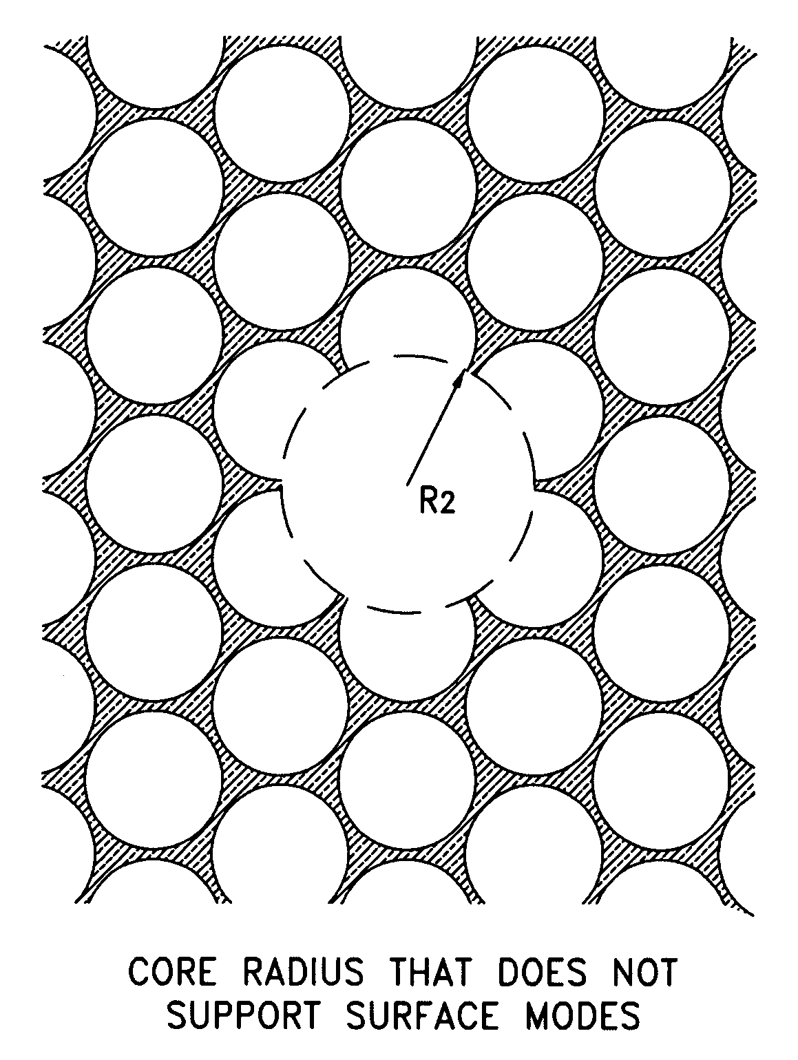
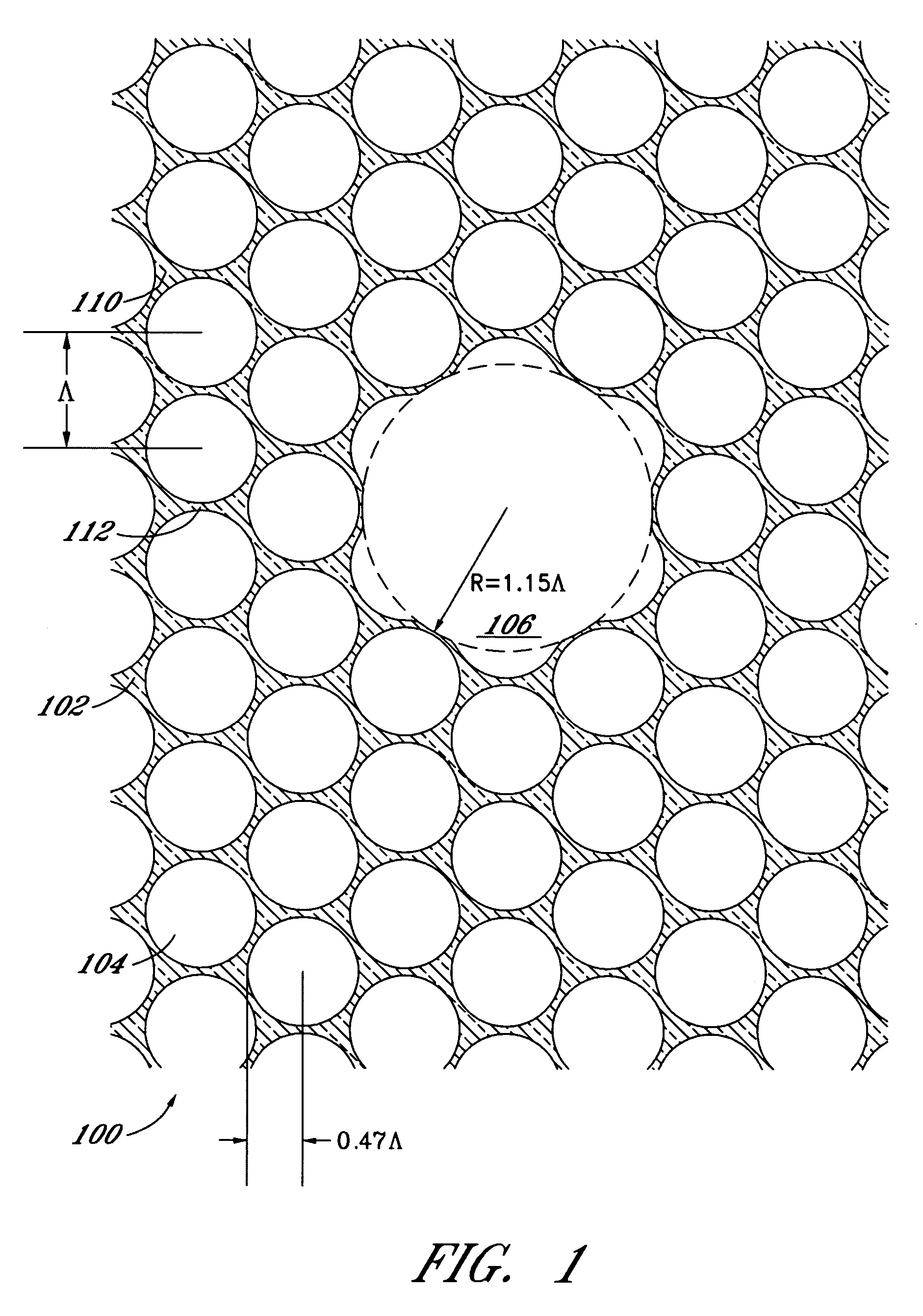
[0011]New geometries are proposed herein for air-core fibers or fibers with a core that has a lower refractive index than the solid portions of the cladding. These geometries have ranges of core characteristic dimensions (e.g., core radii when the core is circular) for which the fiber core supports no surface modes over the entire wavelength range of the bandgap, and only core modes are present. In particular, for a circular core with a radius between about 0.7Λ and about 1.05Λ, where Λ is the hole-to-hole spacing of the triangular pattern, the core in a proposed new geometry supports a single mode and does not support any surface modes. The absence of surface modes suggests that fibers within this range of configuration should exhibit substantially lower losses than current fibers. As further shown below, the existence of surface modes in the defect structure can be readily predicted either from a study of the bulk modes alone or even more simply by a straightforward geometric argument. Because the structure is truly periodic, prediction of the existence of surface modes in accordance with the methods described below is quicker and less complicated than a full analysis of the defect modes.
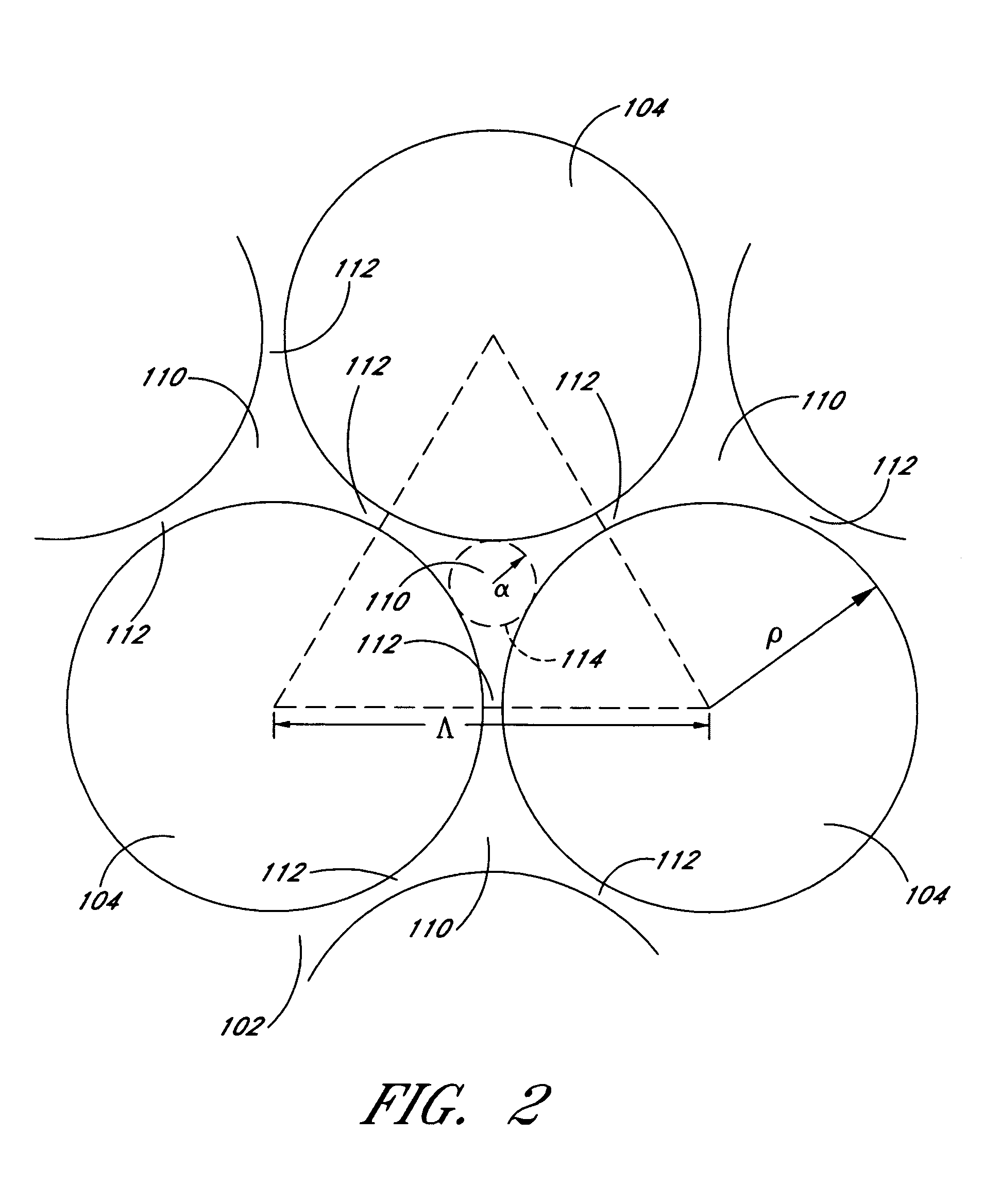
[0012]The methods disclosed herein can be used to predict whether a particular fiber geometry will support surface modes so that fibers can be designed and manufactured that do not support surface modes. In particular, as illustrated below in the detailed description, the presence of surface modes can be avoided by selecting the core radius or other characteristic dimension such that the edge of the core does not cut through any of the circles inscribed in the veins (e.g., the solid intersection regions) of the PBF lattice. The technique works for broad ranges of geometries and hole sizes.

Problems solved by technology

In particular, the propagation loss in an air-core PBF is not limited by the core material, and it is expected that the propagation loss can be exceedingly low.
Since surface modes are inherently lossy due to their high energy density in the dielectric of the fiber, such coupling is a source of propagation loss.
Furthermore, since surface modes occur across the entire bandgap, no portion of the available spectrum is immune to this loss mechanism.
Recent findings have demonstrated that surface modes are a cause of the reduced transmission bandwidth in a 13-dB / km air-core PBF manufactured by Corning.

Method used


Image

  • Method for configuring air-core photonic-bandgap fibers free of surface modes
  • Method for configuring air-core photonic-bandgap fibers free of surface modes
  • Method for configuring air-core photonic-bandgap fibers free of surface modes

Examples


Embodiment Construction

[0040]The following description is based on a photonic band-gap fiber (PBF) with a cladding photonic crystal region comprising a triangular lattice comprising a plurality of circular holes filled with a gas (e.g., air) in silica or other solids, where the holes are spaced apart by a period Λ. Silica-based PBFs are described, for example, in R. F. Cregan et al., Single-Mode Photonic Band Gap Guidance of Light in Air, cited above; Jes Broeng et al., Analysis of air-guiding photonic bandgap fibers, cited above; and Jes Broeng et al., Photonic Crystal Fibers: A New Class of Optical Waveguides, cited above. For simplicity, such fibers are referred to herein as air-hole fibers; however, as discussed above, the following discussions and results are also applicable to photonic-bandgap fibers with a core and / or all or some of the cladding holes filled with other materials besides air (e.g., another gas, a vacuum, a liquid, or a solid) and with solid portions of the cladding made of materials...


PUM

PropertyMeasurementUnit
wavelengthaaaaaaaaaa
refractive indexaaaaaaaaaa

Abstract

Coupling of core modes to surface modes in an air-core photonic-bandgap fiber (PBF) can cause large propagation losses. Computer simulations analyze the relationship between the geometry and the presence of surface modes in PBFs having a triangular hole pattern and identify ranges of core characteristic dimensions (e.g., radii) for which the fiber supports no surface modes (i.e., only core modes are present) over the entire wavelength range of the bandgap. In particular, for a hole spacing Λ and a hole radius ρ=0.47Λ, the core supports a single mode and supports no surface modes for core radii between about 0.68Λ and about 1.05Λ. The existence of surface modes can be predicted simply and expediently by studying either the bulk modes alone or the geometry of the fiber without requiring a full analysis of the defect modes.

Description

RELATED APPLICATIONS[0001]The present application claims the benefit of priority under 35 U.S.C. § 119(e) of U.S. Provisional Application No. 60 / 502,329, filed on Sep. 12, 2003; U.S. Provisional Application No. 60 / 502,390, filed on Sep. 12, 2003; U.S. Provisional Application No. 60 / 502,531, filed on Sep. 12, 2003; and U.S. Provisional Application No. 60 / 564,896, filed on Apr. 23, 2004, which are incorporated by reference herein.BACKGROUND OF THE INVENTION[0002]1. Field of the Invention[0003]The present application is in the field of optical fibers for propagating light, and more particularly is in the field of photonic-bandgap fibers having a hollow core, or a core with a refractive index lower than the cladding materials.[0004]2. Description of the Related Art[0005]Air-core photonic-bandgap fibers (PBFs) have attracted great interest in recent years due to their unique advantages over conventional fibers. In particular, the propagation loss in an air-core PBF is not limited by the ...

Claims


Application Information

Patent Timeline
Patent Type & Authority Patents(United States)
IPC IPC(8): G02B6/032A61K31/135A61K31/137A61K31/4168A61K31/498A61K31/506A61K31/517A61K45/06
CPCA61K31/135A61K31/4168A61K31/498A61K31/506A61K31/517A61K45/06G02B6/02328A61K31/137Y10T428/2913G02B6/02338Y10T428/2929A61K2300/00
Inventor KIM, HYANG KYUNFAN, SHANHUIKINO, GORDON S.SHIN, JONGHWADIGONNET, MICHEL J. F.
Owner THE BOARD OF TRUSTEES OF THE LELAND STANFORD JUNIOR UNIV
Learn More