Energy-absorption system

Inactive Publication Date: 2006-09-26
KOTHMANN ENTERPRISES
View PDF119 Cites 17 Cited by
  • Summary
  • Abstract
  • Description
  • Claims
  • Application Information

AI Technical Summary

Benefits of technology

[0021]For example, one or more shear type cutters may be located to reduce the moment of inertia of beams and thereby to reduce the total amount of energy absorbed per linear foot of travel for each portion of a beam when a thicker metal guardrail beam is used and thus compensate for the increased energy absorbed because of the thickness of the guardrail and vice versa. Thus, the guardrail system may be des

Problems solved by technology

This type of guardrail has several disadvantages, such as for example: (1) it is relatively expensive; and (2) the basic configuration cannot be readily adapted to different thickness of beam or to different materials from which the barrier may be constructed.
Moreover, it is diffi

Method used


Image

  • Energy-absorption system
  • Energy-absorption system
  • Energy-absorption system

Examples


Embodiment Construction

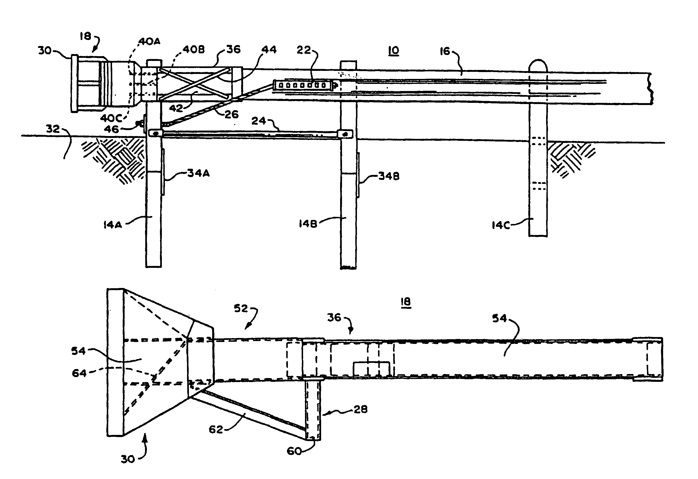
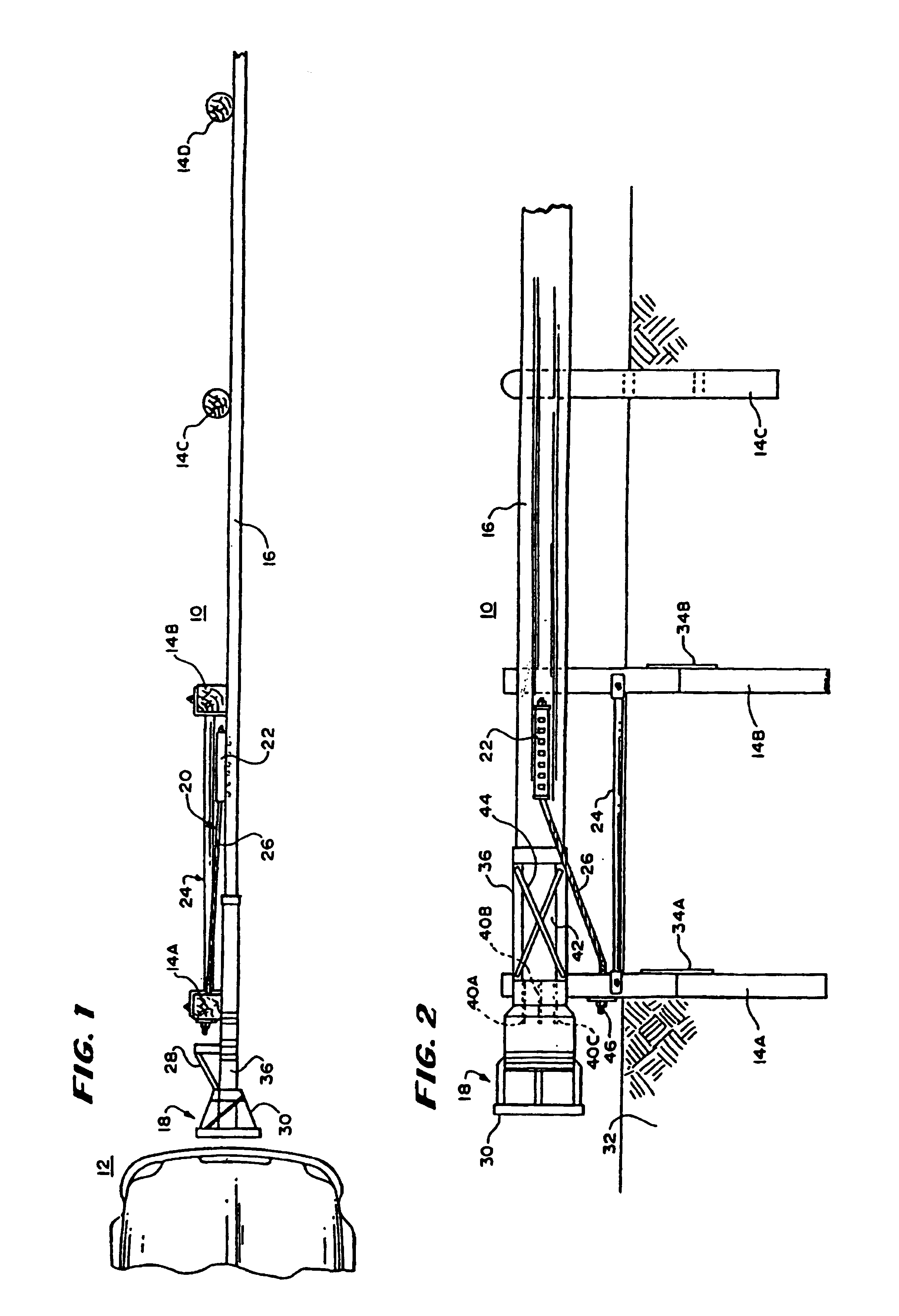
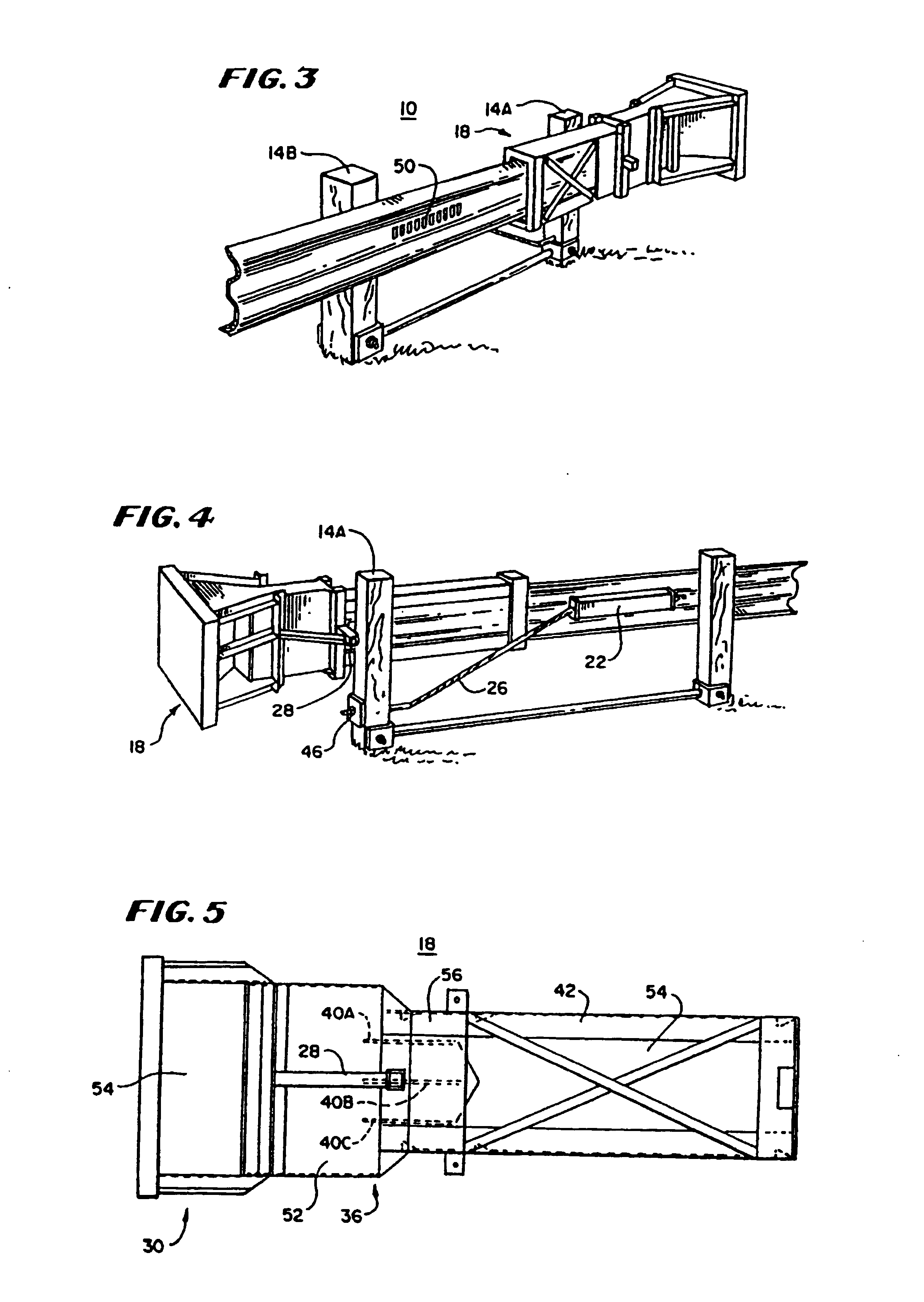
[0040]In FIG. 1, there is shown a plan view of a guardrail system 10 with a vehicle 12 positioned to hit it. The guardrail system 10 includes a plurality of posts, four of which are shown at 14A, 14B, 14C and 14D, a guardrail 16, a terminal assembly 18 and a cable anchoring system 20, with the terminal assembly 18 being at one end of the guardrail 16 and the cable anchoring system connecting the guardrail 16 to a support. The guardrail 16 is mounted to the posts 14A-14D to be substantially parallel to a roadway.

[0041]In this guardrail system, the terminal assembly 18 and the guardrail 16 cooperate together to reduce the likelihood of bodily injury to passengers and guests in the vehicle 12 when the vehicle 12 leaves the roadway and impacts against the guardrail 16 or the terminal assembly 18 at its end. The guardrail 16 may be of any suitable type, but in the preferred embodiment, it includes a conventional W-beam. Similarly, the posts 14A, 14B, 14C and 14D may be of any general typ...


PUM


Abstract

To reduce the danger of bodily harm to occupants of vehicles that leave a roadway, a guardrail system includes an energy-absorption system is provided. The energy-absorption system including a cutting mechanism positioned to cut a guardrail section upon impact by a vehicle to decelerate the vehicle.

Description

REFERENCE TO RELATED APPLICATIONS[0001]This application is a continuation of and claims priority to the filing dare of U.S. patent application Ser. No. 09 / 410,635, filed an Oct. 1, 1999, for ENERGY ABSORPTION SYSTEM, now U.S. Parent 6,505,820 issued on Jan. 14, 2003, which is a divisional of and claims priority to U.S. patent application Ser. No. 08 / 335,153, filed on Nov. 7, 1994, for GUARDRAIL CUTTING TERMINAL, now U.S. Pat. No. 6,022,003.BACKGROUND OF THE INVENTION[0002]This invention relates to guardrails intended to be positioned along a highway to reduce injury to the driver and passenger of vehicles that may accidentally tend to leave the highway.[0003]In one class of guardrail system, each guardrail system includes an elongated barrier and at least one energy-absorbing terminal. The elongated barrier extends parallel to the roadway along the side of the roadway and ends in a terminal. The terminal cooperates with one or more components of the barrier to absorb energy when a v...

Claims


Application Information

Patent Timeline
IPC IPC(8): A01K3/00E01F15/14
CPCE01F15/143
Inventor SICKING, DEAN L.PFEIFER, BRIAN G.
Owner KOTHMANN ENTERPRISES
Why Eureka
Try Eureka