Spread illuminating apparatus adapted to allow light to exit out from both surfaces of light conductive plate

a technology of illuminating apparatus and light conductive plate, which is applied in the direction of lighting and heating apparatus, instruments, and details of portable computers, etc., can solve the problems of wasting electric power of light sources, and achieve the effects of reducing brightness unevenness, improving visibility, and increasing brightness

Inactive Publication Date: 2006-09-26
MINEBEA CO LTD
View PDF19 Cites 13 Cited by
  • Summary
  • Abstract
  • Description
  • Claims
  • Application Information

AI Technical Summary

Benefits of technology

[0017]Consequently, light exiting out from the both major surfaces of the light conductive plate can be effectively utilized, whereby increased brightness, reduced unevenness in brightness and improved visibility over the first major surface of the light conductive plate can be achieved.

Problems solved by technology

In such a case, the two LCD panels may be different in display screen size, which raises a problem with the display device described above with reference to FIG. 12.
As shown in FIG. 11, light PR exiting out from the light conductive plate 11 toward the person to be photographed is not utilized at the non-display area Y and gone uselessly, which means wasted electric power of the light source thus having a critical impact on an electronics device, such as a portable telephone, which strongly demands low power consumption.

Method used


Image

  • Spread illuminating apparatus adapted to allow light to exit out from both surfaces of light conductive plate
  • Spread illuminating apparatus adapted to allow light to exit out from both surfaces of light conductive plate
  • Spread illuminating apparatus adapted to allow light to exit out from both surfaces of light conductive plate

Examples


first embodiment

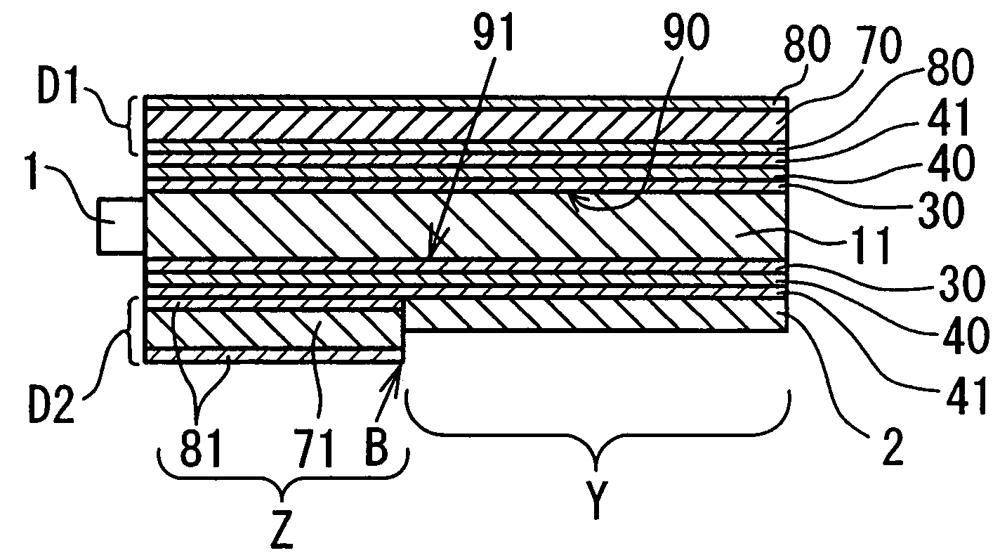
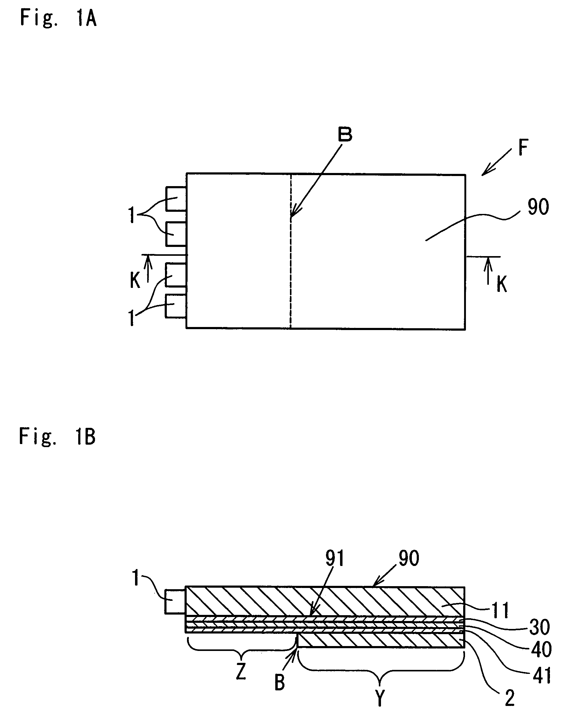
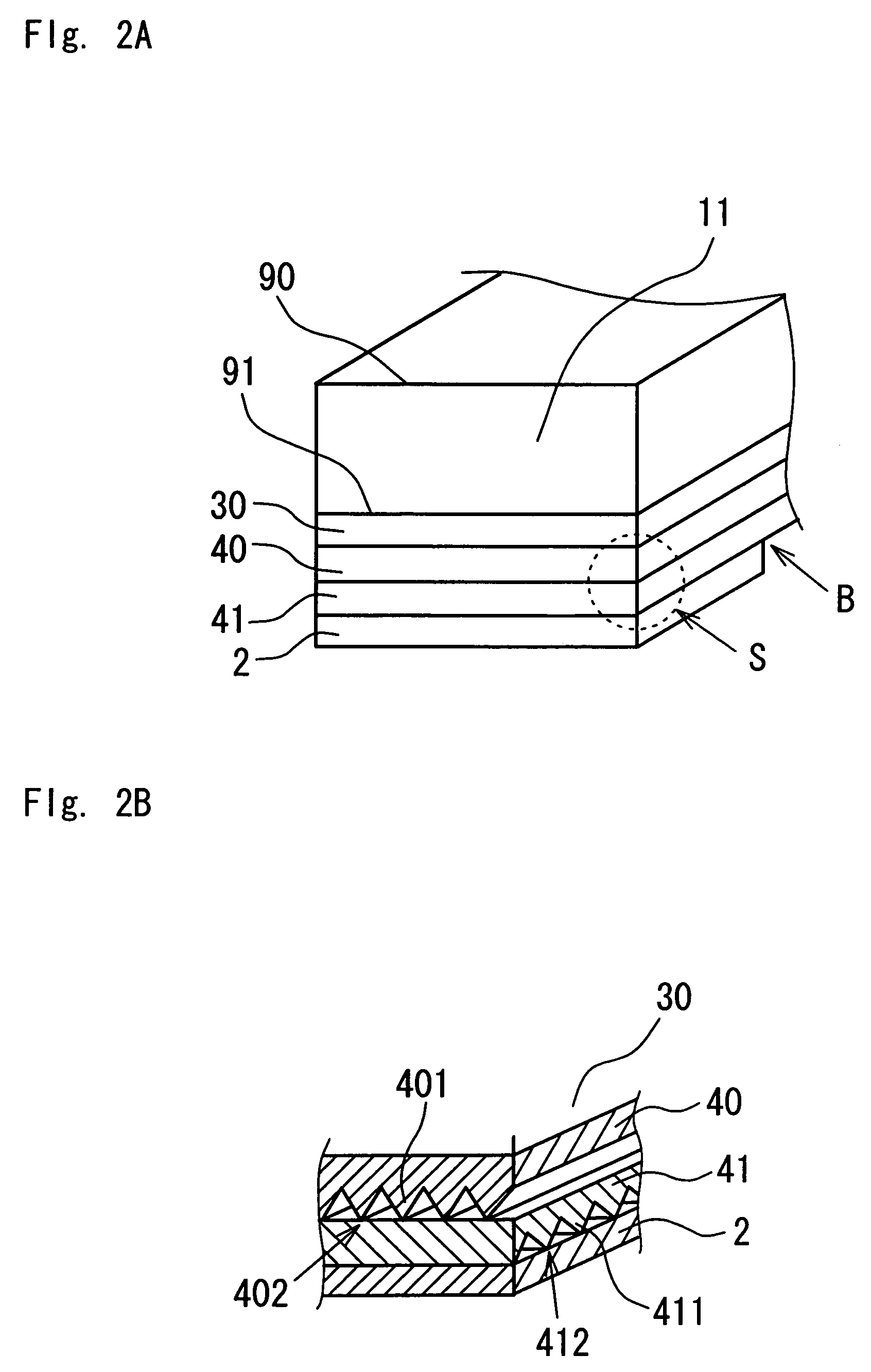
[0031]the present invention will be described with reference to FIGS. 1A and 1B. A light conductive plate 11 has an end surface at which a plurality (four in the figure) of light sources 1, such as light emitting diodes (LEDs), are disposed, and through which light emitted from the light sources 1 is introduced, and has two major surfaces, specifically a first major surface 90 and a second major surface 91 through which the light introduced in the light conductive plate 11 exits out respectively toward two objects (not shown) to be illuminated. An optical sheet unit, which consists of a diffuser sheet 30, and condenser sheets 40, 41, is disposed on at least the second major surface 91 so as to cover the entire area thereof. A reflector plate 2, as a reflecting means, having a smaller area than the second major surface 91 is placed on top of the optical sheet unit. Thus, the optical sheet unit is to cover not only an area Z (hereinafter referred to as “display area”) from which light...

second embodiment

[0046]Referring to FIG. 4, a first example of a reflectance adjusting means comprises a plurality of mechanisms 20 which have a circular shape, are provided on a surface 2a of the reflector plate 2 facing the light conductive plate 11, and which are located at an end area close to the boundary B. The mechanisms 20 are formed by coating the reflector plate 2 with a material, such as white paint, having a lower reflectance than the reflector plate 2. The mechanisms 20 have their area gradually decreasing in accordance with an increase in the distance from the boundary B, whereby the reflector plate 2 has its reflectance gradually decreasing in accordance with a decrease in the distance from boundary B. The size and number of the mechanisms 20 are appropriately determined considering the size and reflectance of the object to be illuminated (the second LCD element D2 in the second embodiment) and the size of the light conductive plate 11. The shape of the mechanisms 20 is not limited to...


PUM

PropertyMeasurementUnit
hazeaaaaaaaaaa
thicknessaaaaaaaaaa
thicknessaaaaaaaaaa

Abstract

A spread illuminating apparatus for illuminating two objects includes: at least one light source; a light conductive plate having the at least one light source at an end surface thereof and defining first and second major surfaces from which light emitted from the at least one light source and introduced in the light conductive plate exits out respectively toward two objects to be illuminated; an optical sheet unit consisting of a diffuser sheet and condenser sheets, and disposed on at least the second major surface so as to cover an entire area thereof; and a reflecting means having a smaller surface area than the second major surface, and disposed directly on top of the optical sheet unit.

Description

BACKGROUND OF THE INVENTION[0001]1. Field of the Invention[0002]The present invention relates to a spread illuminating apparatus, and more particularly to a spread illuminating apparatus in which light exits out from both major surfaces of a light conductive plate.[0003]2. Description of the Related Art[0004]There has been a demand for a display device which has two viewing screens disposed in parallel with each other so as to sandwich an illuminating apparatus, and which is convenient for a situation where an electronics device, such as a notebook personal computer, is operated by a teacher, an instructor or a sales person while pupils, students or customers view images displayed. FIG. 10 is a schematic cross sectional view of a conventional display device for a notebook personal computer, introduced to answer the aforementioned demand. Such a display device is disclosed in, for example, Japanese Patent Application Laid Open No. H10-90678.[0005]Referring to FIG. 10, a display devic...

Claims


Application Information

Patent Timeline
Patent Type & Authority Patents(United States)
IPC IPC(8): F21V7/04G02F1/1333F21V8/00F21Y101/02G02F1/1335G02F1/13357G06F1/16H01P5/00
CPCG02F1/133615G06F1/1647G06F1/1637G06F1/1616G02F2001/133342G02F1/133342A61J3/00A61J7/0076
Inventor MIZUTANI, HITOSHIEGAWA, MOTOJI
Owner MINEBEA CO LTD
Why Eureka
Try Eureka