
Connector for camera module use

a camera module and connector technology, applied in the direction of coupling device connection, television system, engagement/disengagement of coupling parts, etc., can solve the problems of inability to pick up and transmit clear images, inability to solve technical problems, and inability to close vertical gaps, etc., to achieve complete avoidance of gaps between camera modules and connectors, the effect of reducing parts cost and reducing weight and siz

Inactive Publication Date: 2006-09-26
MITSUMI ELECTRIC CO LTD
View PDF15 Cites 32 Cited by
  • Summary
  • Abstract
  • Description
  • Claims
  • Application Information

AI Technical Summary

Benefits of technology

The present invention provides a connector for camera module use that can prevent gaps between the camera module and the connector caused by vertical movement. The connector includes an engaging member and a pushing member that can push the camera module to a bottom face of the connector. The engaging member is engaged with the camera module and prevents it from being disengaged. The pushing member includes elastic members that push the camera module body to the bottom face of the connector. The invention solves the technical problem of gaps formed between the camera module and the connector, which can affect image quality.

Problems solved by technology

However, in the conventional connector for camera module use, the following problems may be encountered.
However, gaps formed in the vertical direction cannot be closed for structural reasons.
As a result, it is impossible to pick up and transmit a clear images.
Therefore, technical problems to be solved are caused.

Method used


Image

  • Connector for camera module use
  • Connector for camera module use
  • Connector for camera module use

Examples


embodiment 1

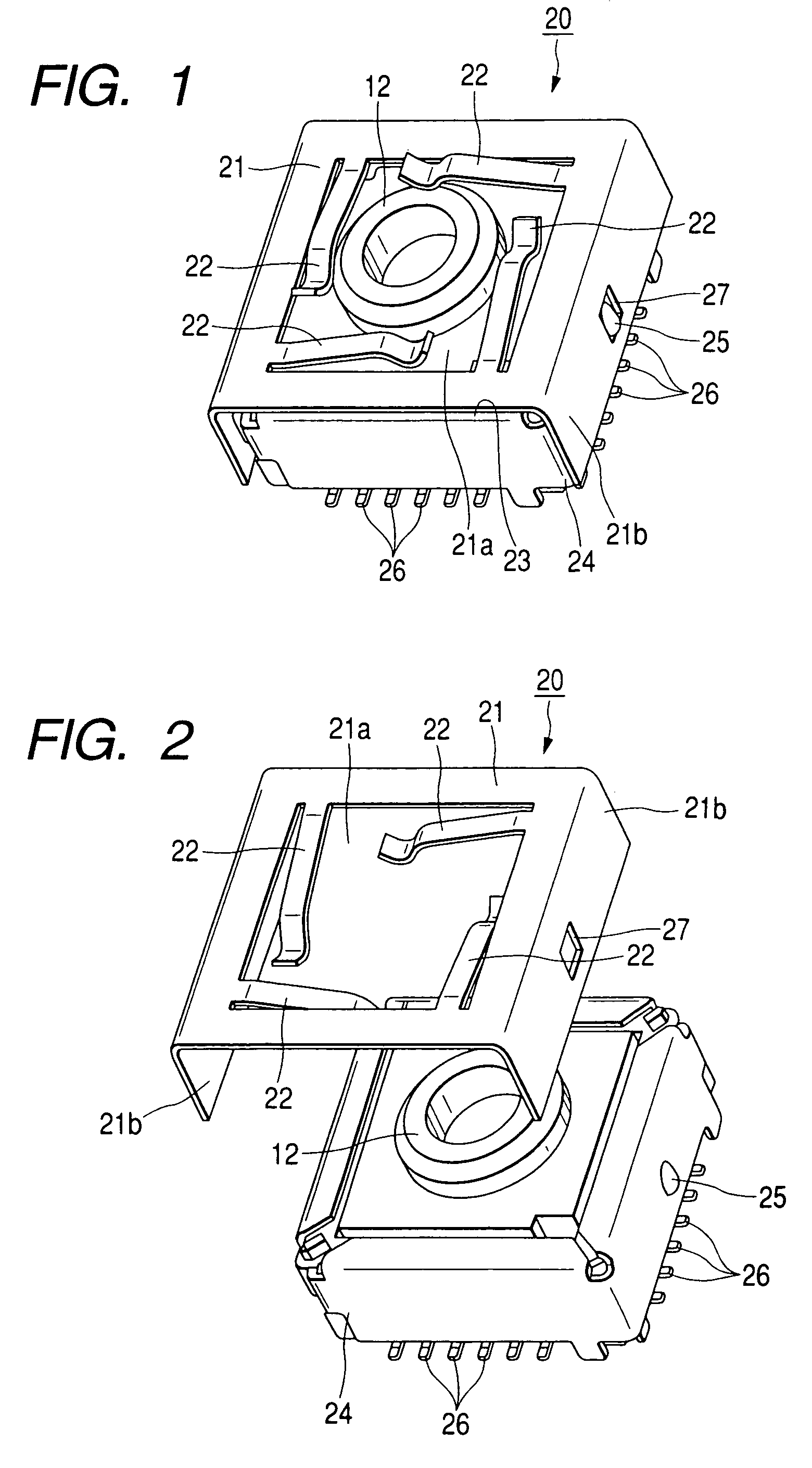
[0034]Referred to FIGS. 1 and 2, an embodiment of the present invention will be described in detail as follows.

[0035]FIG. 1 is an overall perspective view of the connector for camera module use of the first embodiment of the present invention.

[0036]FIG. 2 is an assembled exploded perspective view of the connector for camera module use shown in FIG. 1.

[0037]The connector 20 for camera module use shown in FIGS. 1 and 2 is composed as follows. The connector box 23 to which the connector pins 26, 26 . . . are attached is covered with the shield case 24 made of metal, and the protruding engaging portions 25, 25 provided on the circumferential side of the shield case 24 are engaged with the engaging holes 27, 27 which are open onto both side plates 21b, 21b of the pushing member 21. In this way, the pushing member 21 is engaged with the shield case 24.

[0038]The pushing member 21 is formed into a shape corresponding to the connector box 23, for example, by means of press forming. The entir...

embodiment 2

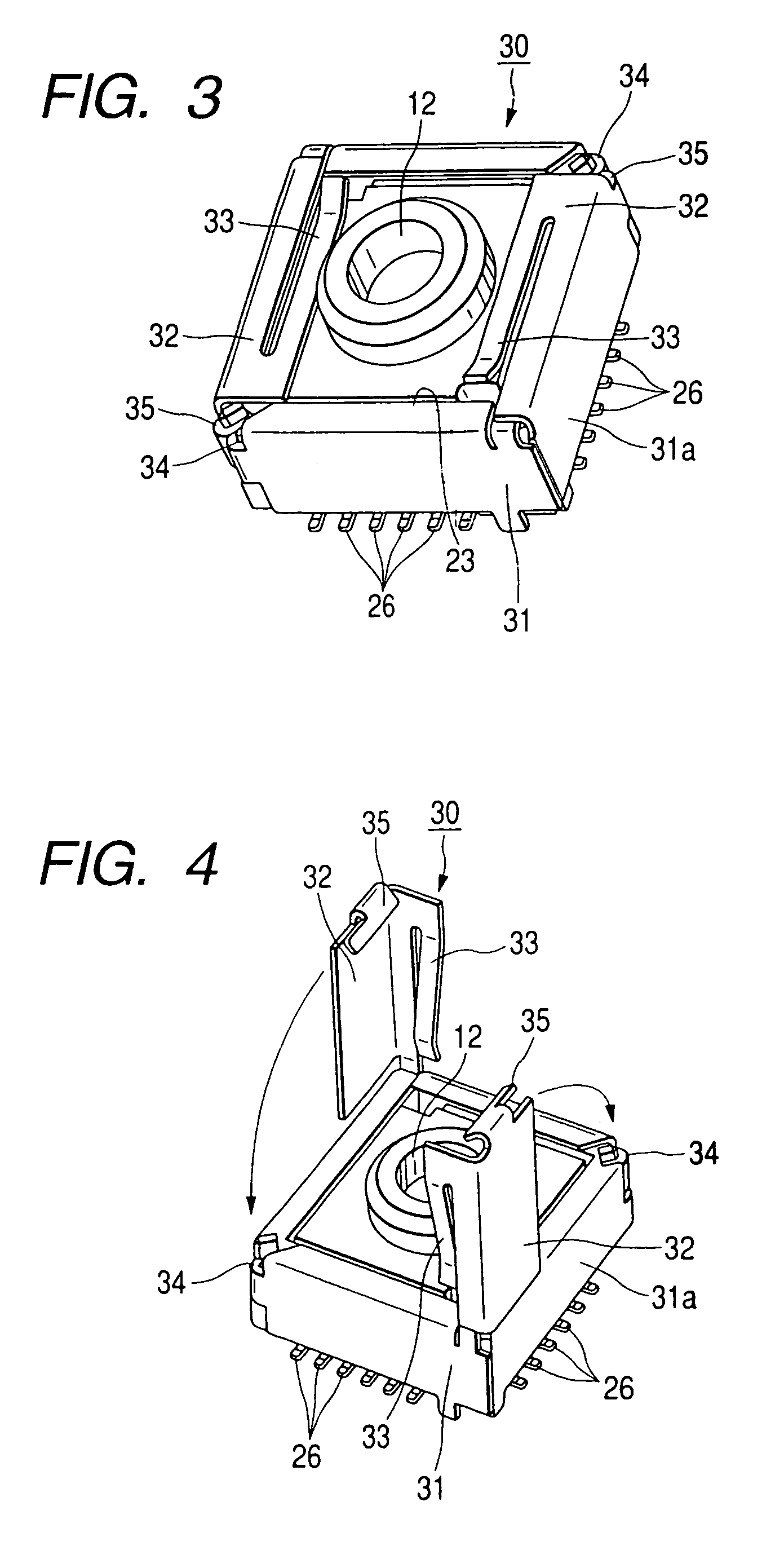
[0042]Next, referring to FIGS. 3 and 4, the second embodiment of the present invention will be explained in detail as follows.

[0043]FIG. 3 is an overall perspective view of the connector for camera module use of the second embodiment of the present invention.

[0044]FIG. 4 is an assembled exploded perspective view of the connector for camera module use shown in FIG. 3.

[0045]The connector 30 for camera module use shown in FIGS. 3 and 4 is composed as follows. The connector box 23 provided with the connector pins 26, 26 . . . is covered and shielded with the shield case 31, and the pushing members 32, 32, in which the same members as the shield case 31 are vertically arranged at the diagonal line corners like a pole and the leaf springs 33, 33 are protruded inside, are arranged and fixed on the circumferential side of the shield case 31 being bent.

[0046]The main bodies of the pushing members 32, 32 are arranged like a pole at the corners of the diagonal line by utilizing portions of the...

embodiment 3

[0052]Referring to the drawings, an embodiment of the present invention will be described in detail as follows.

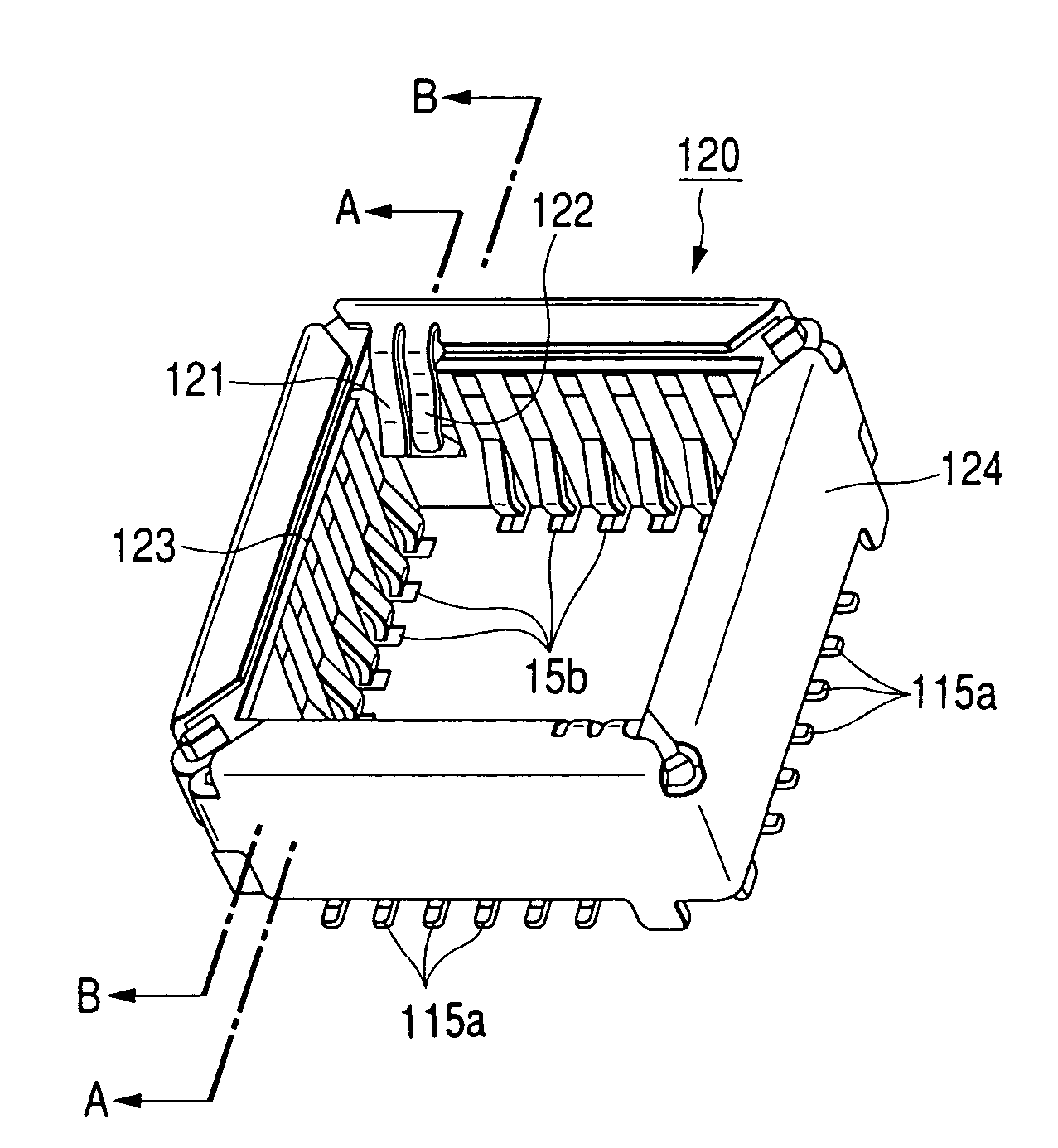
[0053]FIG. 9 is an overall perspective view of the connector for camera module use of an embodiment of the present invention.

[0054]FIG. 10 is a sectional view of the connector for camera module use shown in FIG. 1 taken on line A-A.

[0055]FIG. 11 is a sectional view of the connector for camera module use shown in FIG. 1 taken on line B-B.

[0056]In FIG. 9, reference numeral 120 is a connector for camera module use. The connector 120 for camera module use is composed in such a manner that the connector box 123, to which the connector pins 115a, 115a . . . , 115b, 115b . . . are attached, is covered and fitted with the shield case 124 made of metal. The connector 120 for camera module use includes: an engaging member (lance: movable piece) 121, the shape of which is like a pin, arranged in an empty space between the connector pin 115b on the user side inner wall face and the cor...


PUM


Abstract

To provide a connector for camera module use capable of preventing a defective contact of the connector.A connector for camera module use in which a camera module 12 is accommodated in a connector box 23, which is covered with a shield case, and engaged by an engaging member, the camera module 12 including: a solid image pickup element; a lens unit having a lens for guiding light to the solid image pickup element; and a lens holder by which the solid image pickup element is held, wherein a distance between the lens and the solid image pickup element is adjusted to a predetermined focal distance by the lens holder, and the connector for camera module use comprises a pushing member 21, and the pushing member 21 includes: an opening portion 21a formed at the center, the size of which is larger than that of the lens unit; leaf-spring-shaped elastic members 22, 22 . . . protruding along inner edges of the opening portion; and both side plates 21b, 21b on which an engaging hole 27 to be engaged with an engaging portion 25 formed on a circumferential side of the shield case 24 is formed, wherein the pushing member 21 is formed into a reverse U-shape when it is viewed from the front, and when the pushing member 21 is engaged with the shield case, it pushes the camera module body to a bottom face by elastic forces of the elastic members.

Description

BACKGROUND OF THE INVENTION[0001]1. Field of the Invention[0002]The present invention relates to a connector for camera module use having a solid image pickup element. More particularly, the present invention relates to a connector for camera module use by which the camera module can be stably connected.[0003]2. Description of the Related Art[0004]Concerning the conventional CMOS camera module, as shown in FIG. 5 which is an appearance view of the camera module, the camera module 1 includes a lens holder 3, wherein the lens holder 3 is composed of a holder base 4, the shape of which is a substantially rectangular parallelepiped, and a lens joining portion 5, the shape of which is a substantially hollow cylinder, which is provided at the center of an upper face of the holder base 4. In the camera module, the sensor 6 is accommodated which is composed of a solid image pickup element such as CMOS, the shape of which is a rectangular parallelepiped smaller than the holder base 4. The le...

Claims


Application Information

Patent Timeline
Patent Type & Authority Patents(United States)
IPC IPC(8): H01R13/62H04N5/225
CPCH04N5/2253H04N5/2251H01R23/6873H01R12/7076H01R13/658H04N23/54
Inventor NISHIO, ATSUSHIKAWASAKIKARAHASHI, SATORU
Owner MITSUMI ELECTRIC CO LTD
Learn More