Gear unit for the drive of a rotation tube

Inactive Publication Date: 2006-09-26
SIEMENS AG
View PDF22 Cites 26 Cited by
  • Summary
  • Abstract
  • Description
  • Claims
  • Application Information

AI Technical Summary

Problems solved by technology

The motor-side driving pinion and the intermediate shafts are supported at multiple locations by bearings, whereby this arrangement is associated with an increased production-and installation-effort.
Higher power outputs can only be achieved with an enlargement of th

Method used


Image

  • Gear unit for the drive of a rotation tube
  • Gear unit for the drive of a rotation tube
  • Gear unit for the drive of a rotation tube

Examples


Embodiment Construction

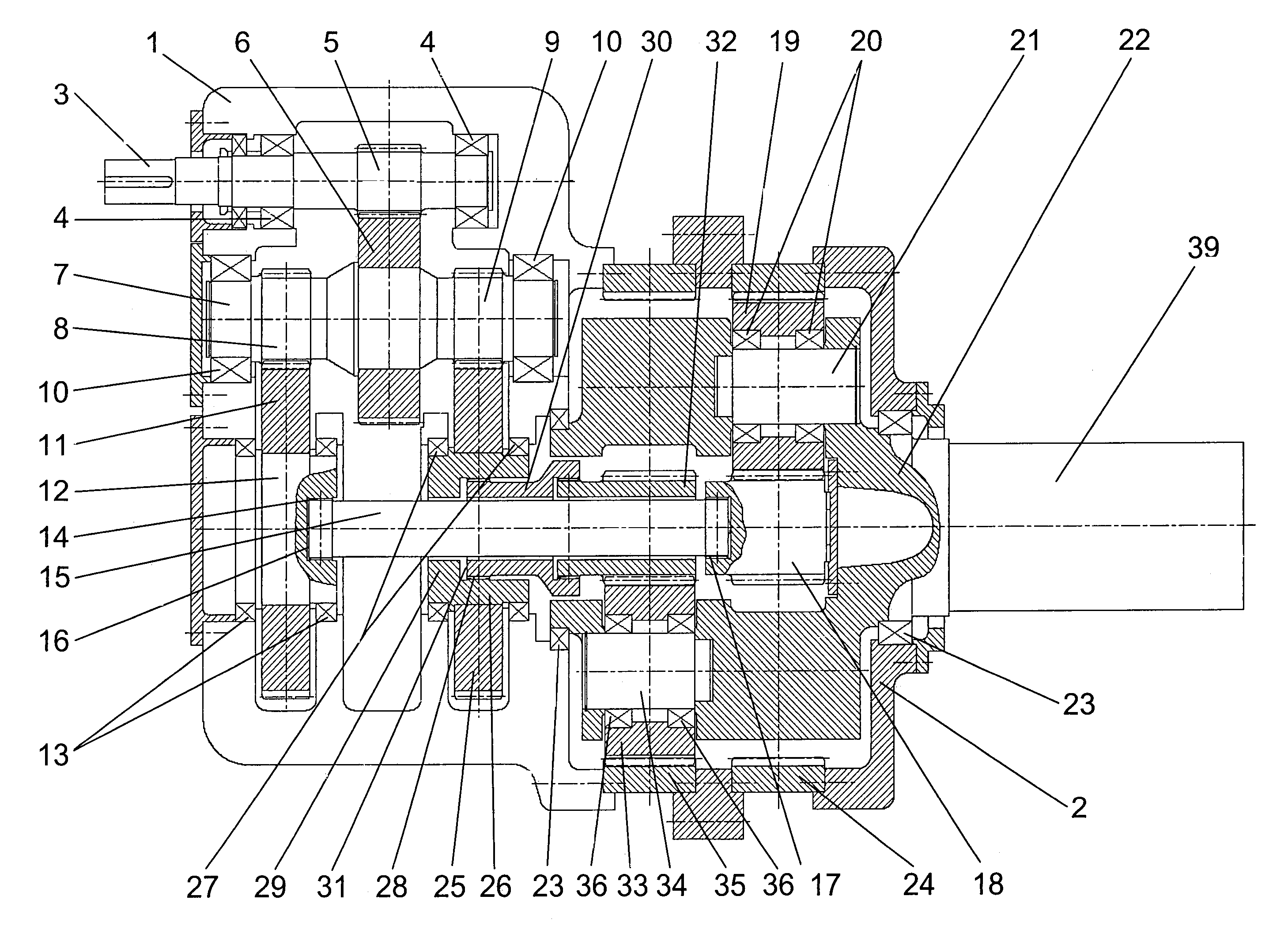
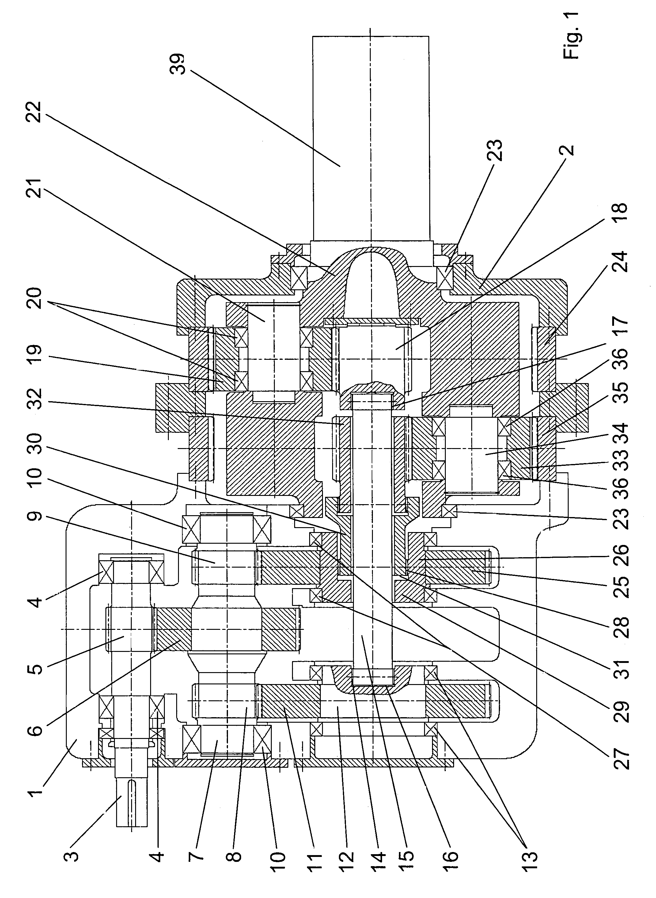
[0014]The gear unit shown in FIG. 1 serves as the drive of a tube mill with a straight line flow or stream of the drive output along the central axis of the tube mill. The gear unit comprises an input side power distribution stage and a take-off load-summing stage. The gear unit is mounted in a housing which is comprised of two housing parts 1, 2 whose interiors are spaced from one another. The housing part 1 comprises a horizontal parting line and receives therein the input side power distribution stage. The other housing part 2 receives therein the take-off load-summing stage. The interior space separation permits the implementation of differing concepts for the provision of lubrication to the components of the gear unit. Preferably, the oil lubrication is provided to the rapidly running parts of the power distribution stage in the housing part 1 by a closed circuit pressure lubrication that is not illustrated herein. With respect to the load stage which, as will be described in m...


PUM


Abstract

A gear unit for the drive of a rotating tube is provided with a drive shaft and a power distributing gear unit stage that is configured as a helical gear unit with an intermediate shaft having mounted thereon two helical pinions. A load-summing gear unit stage with a take-off shaft is operated downstream of the gear unit stage. In this connection, the take-off shaft is on the central axis of the driven rotating tube. The load-summing gear unit stage is comprised of two parallel operated planetary gear units each having a sun gear, planetary gears each disposed on a respective planetary axle, a hollow gear and a common planet carrier that is configured as a single piece and connected with the take-off shaft. The planetary axles of both planetary gear units in the common planet carrier are spaced from one another and offset from one another. The intermediate shaft of the helical gear unit and the planetary gear units are supported in floating bearing arrangement, whereby the helical gear unit and the planetary gear units form a symmetrical planetary gear unit combination.

Description

BACKGROUND OF THE INVENTION[0001]The invention relates to a gear unit for the drive of a rotation tube.[0002]Drive solutions for rotating tubes, such as tube mills or rotary kilns, are characterized along the drive trains thereof by the characteristic configuration beginning with a motor, a coupling, a step-down or speed reducing teeth gear unit, and the thereto coupled tube mill. The gear unit converts the torque of the drive source, which is most typically configured as an electric motor, and, additionally, modulates the output via setting of the speed transmission ratio to that required to achieve the desired output rate of rotation, which is often dictated by the material to be milled by the tube mill.[0003]DE 27 23 319 A1 discloses a two-step multi-path cylindrical gear transmission via which, by means of an inner power distribution, a central drive for tube mills, material size reducers, and similar rotating tubes is created. The distribution of power makes possible an increas...

Claims


Application Information

Patent Timeline
IPC IPC(8): F16H37/06F16H1/22F16H37/08F16H57/08
CPCF16H37/0833F16H57/082F16H1/22F16H1/28F16H2001/289F16H1/46
Inventor UEBBING, DIETMAR
Owner SIEMENS AG
Why Eureka
Try Eureka