Electro-cauterizing cannula assembly for use with power-assisted liposuction instruments

a technology of electric cauterization and power-assisted liposuction, which is applied in the field of electric cauterization cannula assembly for use with power-assisted liposuction instruments, can solve the problems of inability to use a variety of cannulas, inability to achieve high-effective fat aspiration, and inability to achieve high-efficiency liposuction, so as to achieve the effect of increasing safety and not promoting physical fatigu

Inactive Publication Date: 2006-09-26
CUCIN ROBERT L
View PDF49 Cites 23 Cited by
  • Summary
  • Abstract
  • Description
  • Claims
  • Application Information

AI Technical Summary

Benefits of technology

[0009]Thus, it is a primary object of the present invention to provide an improved method and apparatus for performing liposuction which assists the surgeon in the removal of fat and other subcutaneous tissue (such as but not restricted to gynecomastia) from surrounding tissue, with increased safety and without promoting physical fatigue.

Problems solved by technology

Due to the trauma involved during the procedure, the patients' skin, turns black and blue for several weeks.
Due to the physically exacting nature of the procedure, the surgeon typically comes out of an operating room extremely tired and suffers from muscular fatigue, which prevents him from performing, for some time thereafter, the delicate operations involved in ordinary plastic surgery.
Although this is a less physically demanding procedure, the surgeon must thrust the cannula even more times through each tunnel to achieve the desired effect and hence is still easily fatigued and prevented him from performing, for some time thereafter, the delicate operations involved in ordinary plastic surgery.
In addition to the device's overall construction posing difficulties in assembly, cleaning and sterilization, use with a variety of cannulas and highly effective fat aspiration does not appear possible.

Method used


Image

  • Electro-cauterizing cannula assembly for use with power-assisted liposuction instruments
  • Electro-cauterizing cannula assembly for use with power-assisted liposuction instruments
  • Electro-cauterizing cannula assembly for use with power-assisted liposuction instruments

Examples


first embodiment

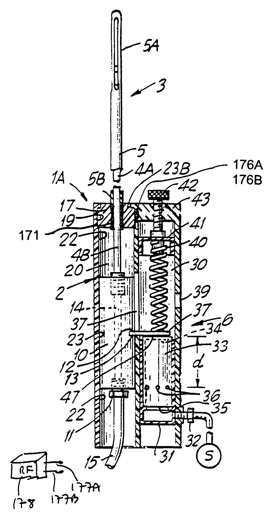
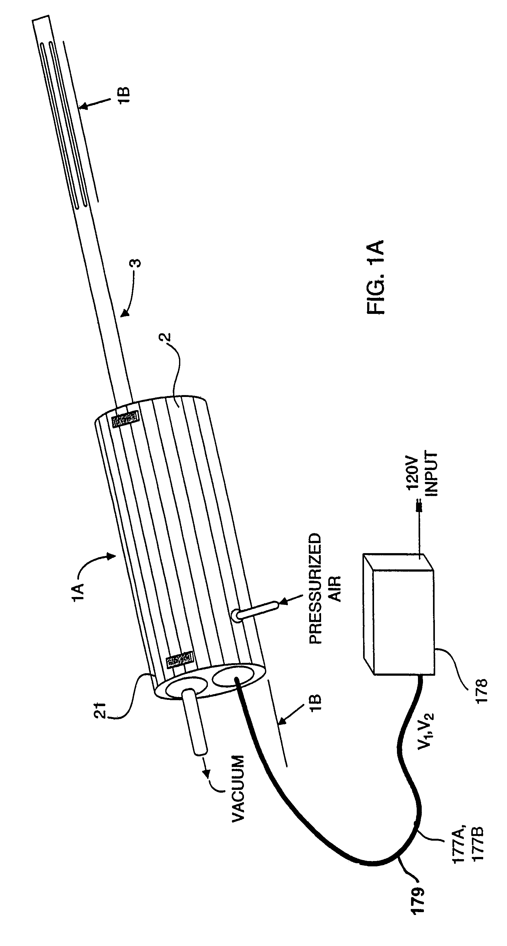
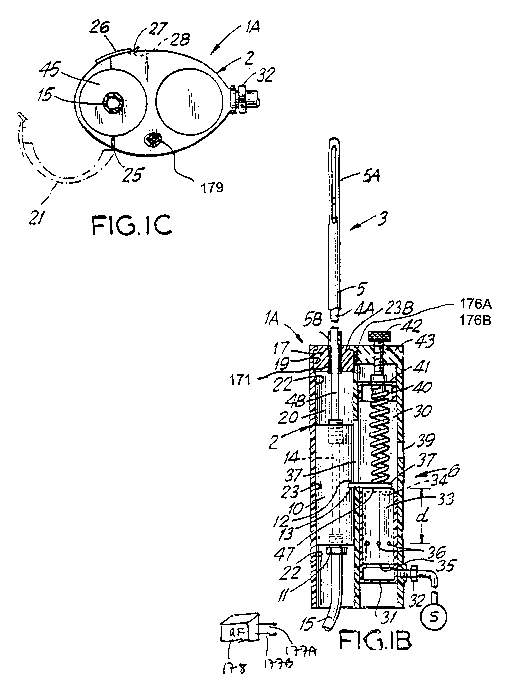
[0081]With reference to FIGS. 1A through 3D, the liposuction device of the present invention will be described. In general, liposuction device 1A comprises a hand-holdable housing 2, a detachable electro-cauterizing cannula assembly 4 having inner and outer cannulas 4 and 5, and a reciprocation means 6 for causing inner cannula 4 to reciprocate means 6 for causing inner cannula 4 to reciprocate relative to outer cannula 5, which is stationarily disposed with respect to housing 2. This arrangement effectuates periodic displacement of the general location of aspiration along the cannula assembly through the reciprocating movement of inner cannula 4, while permitting electro-cauterization of aspirated tissue during operation of the liposuction device.

[0082]As illustrated in greater detail in FIGS. 1B, and 2A through 2E, the electro-cauterizing cannula assembly 3 of the present invention comprises an electrically-conductive inner cannula 4 and a non-conductive outer cannula 5, each comp...

third embodiment

[0108]In order to selectively adjust the amount of cannula excursion permitted during a liposuction operation, piston-type motor 6 can be modified, as shown in FIG. 5, to produce the liposuction device of the present invention. As illustrated in FIG. 5, the basic structure of liposuction device 1C is similar to that shown in FIGS. 1A through 1C, except that a user-adjustable intermediate housing wall 88 is disposed between the inner walls 31A of chamber housing 31 and the outer walls 34A of movable piston 34. Intermediate housing wall 87 is operably associated with an excursion selection means realized as a slidable member 88 fixedly attached to the upper portion of intermediate housing wall 59. Preferably, slidable member 88 extends through a slot 89 formed in the wall of housing 2 and can be slid, for example, by movement of the surgeon's thumb. The function of intermediate housing wall 87 is to effectively raise the height of the chamber housing wall, and thus selectively increas...

seventh embodiment

[0123]Referring to FIGS. 9A through 9F, there is illustrated yet the liposuction device of the present invention. In general, liposuction device 1G has a pistol-shaped housing 110 which comprises a barrel portion 111 and a detachable handle portion 112. Instead of using a reciprocating piston motor to translate inner cannula 4′ relative to housing 100, this embodiment utilizes a rotary-type motor 113. In operative association with a cam mechanism, generally indicated by reference numeral 114, rotary-type motor 113 causes actuation element 115 to cyclically slide back and forth and cause inner cannula 4′ to periodically reciprocate relative to barrel portion 111 of the pistol-shaping housing.

[0124]As illustrated in FIGS. 9B through 9D, barrel portion 111 of the housing comprises a cannula cavity 116 adapted for slidably receiving cylindrically-shaped base 17 of inner cannula 4′, in a manner described hereinabove. Cannula cavity 116 is also provided with a longitudinally extending acc...


PUM


Abstract

An electro-cauterizing cannula assembly for use in a power-assisted liposuction instrument having a hand-holdable housing and a mechanism for reciprocating the cannula assembly. The electro-cauterizing cannula assembly includes an inner and an outer cannula, each having a distal and proximal end and at least one aspiration aperture about the distal end. The inner cannula is disposed within the outer cannula and the inner and outer aspiration apertures are in at least partial registration to form an effective aspiration aperture. During aspiration of tissue, high-voltage RF power signals are supplied to the inner and outer cannulas to effect hemostasis about the reciprocating aspiration aperture. Such hemostasis is achieved by causing protein molecules within aspirated tissue to coagulate in response to the high-voltage RF signals being supplied across the reciprocating cannulas. The cannula assembly is releasably detachable from the hand-holdable housing to facilitate cleaning and sterilization of the same.

Description

RELATED CASES[0001]The present Application is a Continuation of application Ser. No. 09 / 993,297 filed Nov. 19, 2001 now U.S. Pat No. 6,652,522; which is a Continuation of application Ser. No. 08 / 976,073, filed Nov. 21, 1997, now U.S. Pat. No. 6,346,107, which is a Continuation-in-Part of copending application Ser. No. 08 / 882,927 filed Jun. 26, 1997, now U.S. Pat. No. 5,795,323, which is a Continuation of application Ser. No. 08 / 307,000 filed Sep. 16, 1994, now U.S. Pat. No. 5,643,198, which is a Continuation of application Ser. No. 07 / 627,240 filed Dec. 14, 1990, now U.S. Pat. No. 5,348,535. Each said Application is incorporated herein by reference as if set forth in its entirety.FIELD OF INVENTION[0002]The present invention relates generally to a method and apparatus for performing liposuction and more particularly to a method and apparatus for performing liposuction in a mechanically assisted manner using powered expedients.BRIEF DESCRIPTION OF THE PRIOR ART[0003]Suction lipectomy...

Claims


Application Information

Patent Timeline
Patent Type & Authority Patents(United States)
IPC IPC(8): A61B18/18A61M1/00A61B17/32
CPCA61B17/32002A61M1/008A61B2018/00464A61M2202/08A61M2205/106A61M2202/0014A61M1/89A61M1/84
Inventor CUCIN, ROBERT L.
Owner CUCIN ROBERT L
Why Eureka
Try Eureka