Electrical power tool having a motor control circuit for providing control over the torque output of the power tool

a technology of torque output and power tool, which is applied in the direction of electric controllers, ignition automatic control, instruments, etc., can solve the problems that other conventionally controlled power tools with comparable-sized motors cannot achieve, and achieve the effect of limiting the magnitude of torque spikes and greater potential energy

Inactive Publication Date: 2006-09-26
BLACK & DECKER INC
View PDF35 Cites 106 Cited by
  • Summary
  • Abstract
  • Description
  • Claims
  • Application Information

AI Technical Summary

Benefits of technology

[0029]Finally, a further alternative embodiment of the simplified version of the present invention is disclosed that provides a separately adjustable control knob for varying the frequency of the PWM signal. More particularly, the trigger switch in this embodiment functions in a conventional manner to control the duty cycle of the PWM signal. An additional operator actuable knob or dial, preferably located on the top of the drill, is provided for selectively setting the frequency of the PWM signal. Thus, for example, when driving small screws requiring more control, a moderately low frequency (e.g., 50 Hz) can be used which reduces the maximum off time between successive pulses and thereby limits the magnitude of the torque spikes applied to the screw. However, when setting large screws, a lower frequency (e.g., 10 Hz) can be selected which results in sufficiently long off periods to enable the gear train to completely relax, thereby allowing the subsequent build-up of greater potential energy and the application large torque bursts to the screw. Additionally, the operator can simply set the frequency to a normal high PWM frequency level (e.g., 12 KHz) for operation as a conventional variable speed drill.

Problems solved by technology

This technique further has been found to be extremely effective in “breaking loose” tightly set wood screws and the like, which other conventionally controlled power tools having comparable-sized motors are unable to achieve.

Method used


Image

  • Electrical power tool having a motor control circuit for providing control over the torque output of the power tool
  • Electrical power tool having a motor control circuit for providing control over the torque output of the power tool
  • Electrical power tool having a motor control circuit for providing control over the torque output of the power tool

Examples


Embodiment Construction

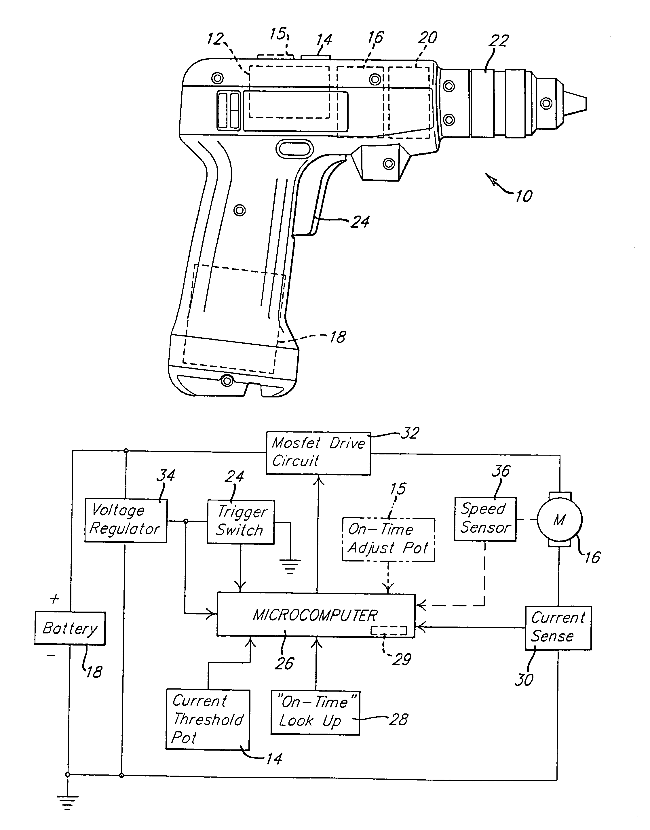
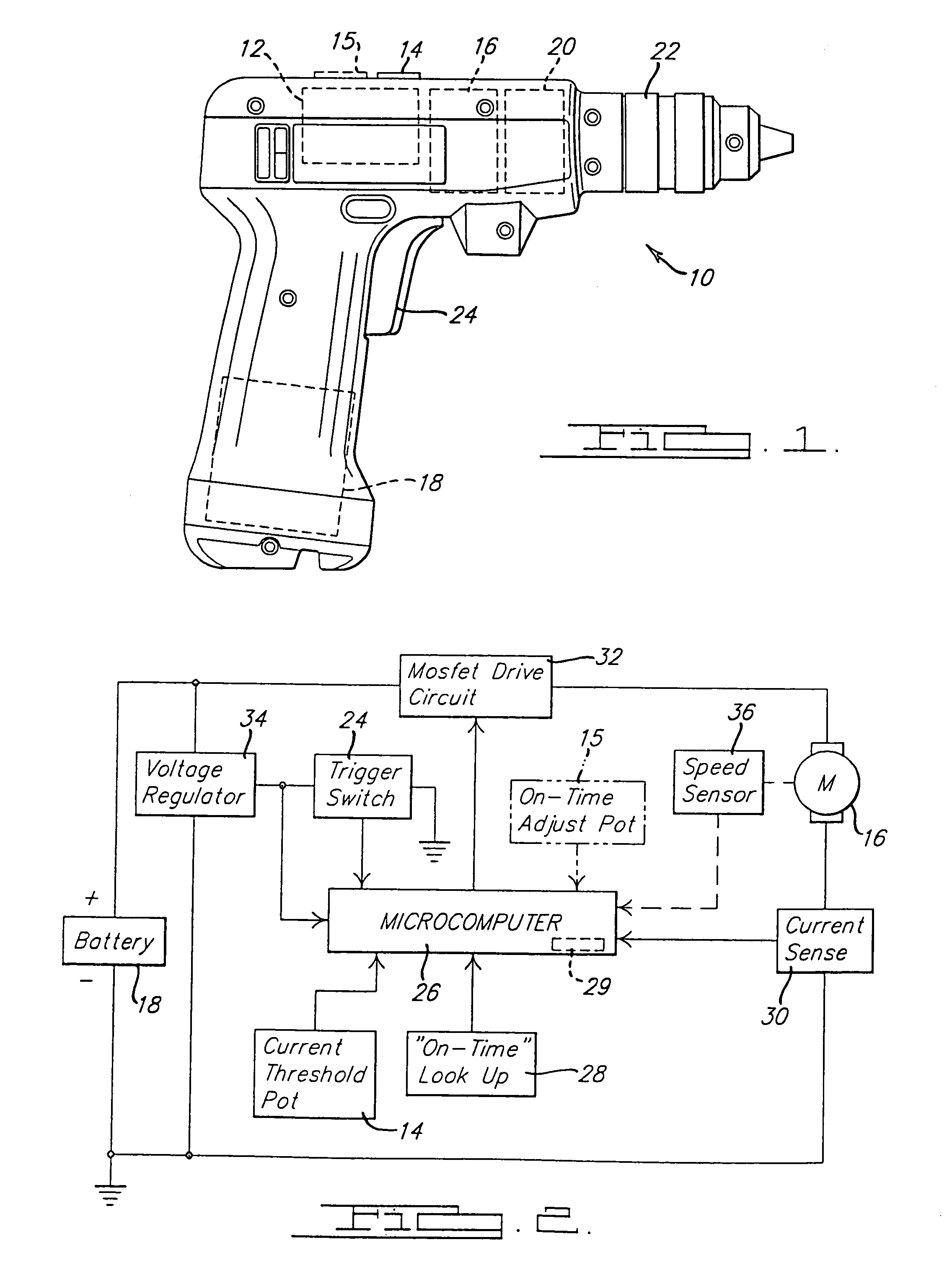
[0044]Referring to FIG. 1, an electrically driven power tool in the form of a cordless (i.e., battery driven) variable speed power drill 10 incorporating an electronic control circuit 12 in accordance with preferred embodiments of the present invention is illustrated. As will readily be appreciated by those skilled in the art, the motor control circuit taught by the present invention is adaptable to other types of electrical power tools, such as power screwdrivers, electric pop rivet guns, and the like. The control circuit 12 includes a current threshold potentiometer 14 which is disposed in a convenient position on the drill 10 to allow an operator to conveniently adjust the potentiometer 14 as needed. The function of this potentiometer 14 will subsequently be described in greater detail.

[0045]Optionally included is an on-time adjustment potentiometer 15 which may be used in lieu of potentiometer 14 in an alternative preferred embodiment of the present invention. The on-time potent...


PUM


Abstract

A power tool such as an electric drill typically contains a gear train that couples the output spindle of the motor to the tool bit-receiving chuck. The control circuit for the power tool is operable in a ratcheting or pulse mode that causes the output spindle to rotate in discrete incremental amounts. Corresponding methods for controlling the operation of the electric motor of a power tool are also disclosed.

Description

[0001]This application is a continuation of application Ser. No. 10 / 166,805, filed Jun. 11, 2002, which is a continuation of application Ser. No. 08 / 834,774, filed Apr. 3, 1997, now U.S. Pat. No. 6,424,799, which is a continuation of Ser. No. 08 / 369,497, filed Jan. 6, 1995, now abandoned, which is a continuation-in-part of Ser. No. 08 / 087,932, filed Jul. 6, 1993, now U.S. Pat. No. 5,440,215.TECHNICAL FIELD[0002]This invention relates to electrically driven power tools and, in particular, to a power tool such as a variable speed drill having a motor control that is adapted to increase and better control the effective torque output of the tool.BACKGROUND OF THE INVENTION[0003]Electrical power tools, such as variable speed drills and power screwdrivers, typically include a motor control circuit that is adapted to control the speed of the output spindle of the tool by controlling the amount of current supplied to the motor. The desired motor speed is usually selected by the operator by ...

Claims


Application Information

Patent Timeline
Patent Type & Authority Patents(United States)
IPC IPC(8): H02P7/00B23P19/06B25B21/00B25B23/14B25B23/147B25F5/00
CPCB23P19/066B25B21/00B25B21/004B25B23/147B25F5/001B25B23/1415Y10S388/937Y10S388/93
Inventor GILMORE, ALAN A
Owner BLACK & DECKER INC
Why Eureka
Try Eureka