Data communication system, controller device and data communication method

a data communication and controller technology, applied in the field of data communication systems, can solve problems such as difficulty in downsizing the whole system, and achieve the effects of reducing power consumption of voltage level generation circuits, and increasing power consumption

Inactive Publication Date: 2006-09-26
COLLABO INNOVATIONS INC
View PDF8 Cites 18 Cited by
  • Summary
  • Abstract
  • Description
  • Claims
  • Application Information

AI Technical Summary

Benefits of technology

[0025]Preferably, the first transmitter circuit changes the first operation voltage in accordance with the first transmitting signal with causing a difference between a period when the first operation voltage has potential corresponding to a logical “H” level and a period when the first operation voltage has potential corresponding to a logical “L” level. When the period when the first operation voltage has potential corresponding to a logical level necessary to consume larger power is shorter, the power consumption of the voltage level generation circuit can be reduced. For example, if the voltage level generation circuit has a circuit configuration in which larger power is necessary for generating potential corresponding to a logical “H” level, the power consumption of the voltage level generation circuit can be reduced by setting the period of the potential corresponding to the “H” level to be shorter than that corresponding to the “L” level.
[0026]Preferably, the first signal detection circuit includes a high-pass filter for receiving a voltage in which a change is to be detected and detecting an edge of the voltage. In this case, in order to identify the logical level of the transmitting signal superimposed on the second operation voltage of the data carrier device or superimposed as a voltage difference on the voltage between the first and second contacts, the edge of the second operation voltage or the voltage between the first and second contacts can be detected. Thus, the data extraction can be eased.

Problems solved by technology

Since the conventional data communication system thus needs four contacts for the data communication, it is difficult to downsize the whole system.

Method used


Image

  • Data communication system, controller device and data communication method
  • Data communication system, controller device and data communication method
  • Data communication system, controller device and data communication method

Examples


embodiment 1

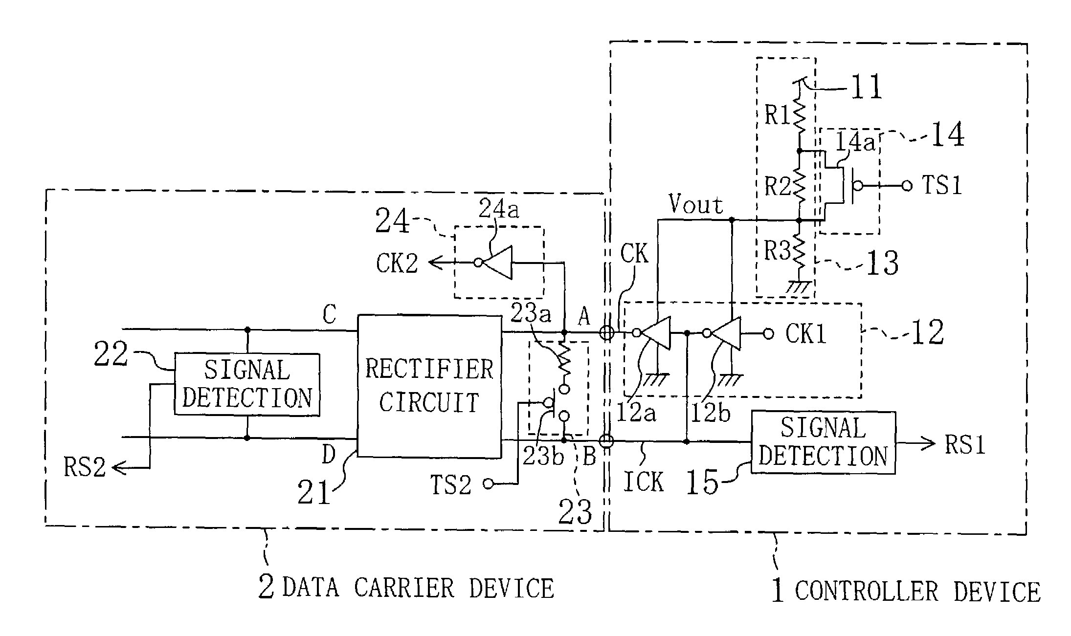
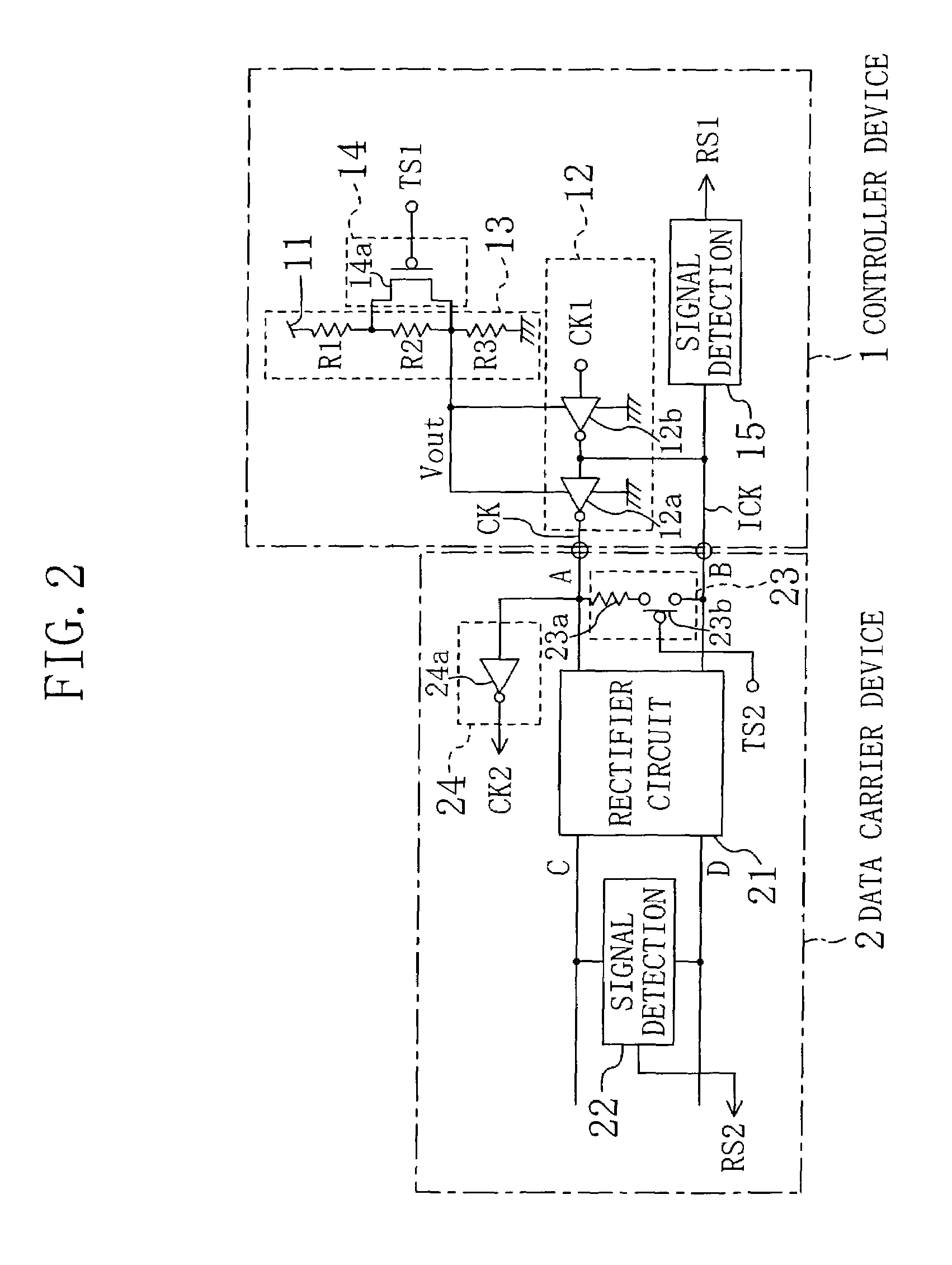
[0053]FIG. 2 shows the structure of a data communication system according to Embodiment 1 of the invention. In the data communication system shown in FIG. 2, a controller device 1 and a data carrier device 2 perform data communication therebetween through two contacts A and B.

[0054]The controller device 1 includes a power supply line 11 for supplying power; a clock generation circuit 12 for generating a clock pulse signal CK (hereinafter referred to as the signal CK) and an inverted clock pulse signal ICK (hereinafter referred to as the signal ICK) in a phase reverse to that of the signal CK and supplying these signals to the first and second contacts A and B, respectively; a voltage level generation circuit 13 for converting the voltage from the power supply line 11 and supplying the converted voltage to the clock generation circuit 12 as a first operation voltage Vout; a first transmitter circuit 14 for changing the first operation voltage Vout generated by the voltage level gener...

embodiment 2

[0069]FIG. 4 shows the structure of a data communication system according to Embodiment 2 of the invention. In FIG. 4, like reference numerals are used to refer to like elements shown in FIG. 2 and the detailed description is omitted.

[0070]As compared with the structure of FIG. 2, in a controller device 1A of FIG. 4, a clock generation circuit 12A that outputs the signal CK alone but does not output the signal ICK is provided instead of the clock generation circuit 12. Also, a second signal detection circuit 15A for detecting, as the second receiving signal RS1, change of the voltage amplitude on the terminal for outputting the first operation voltage Vout of the voltage level generation circuit 13 is provided instead of the second signal detection circuit 15. The clock generation circuit 12A includes one inverter 12c, so as to output a signal in a phase reverse to that of the operation clock CK1 of the controller device 1A as the signal CK to the first contact A. The amplitude of t...

embodiment 3

[0083]FIG. 8 shows the structure of a data communication system according to Embodiment 3 of the invention. In FIG. 8, like reference numerals are used to refer to like elements used in FIG. 2 or 4, and the detailed description is omitted.

[0084]As compared with the structure of FIG. 4, in a controller device 1B of the data communication system of FIG. 8, the clock generation circuit 12A is omitted and the output voltage Vout of the voltage level generation circuit 13 is output to the first contact A as a signal voltage.

[0085]Also, a data carrier device 2B of FIG. 8 includes, in addition to the second transmitter circuit 23, a series regulator 25 for stabilizing an operation voltage generated from the signal voltage Vout supplied from the controller device 1B to the first contact A; a first signal detection circuit 26 for detecting change of the signal voltage between the first and second contacts A and B as the first receiving signal RS2; and a clock generation circuit 27 for genera...


PUM


Abstract

In a controller device, when a first transmitting signal is at a “L” level, a first operation voltage is high and the amplitude of signals CK and ICK is large, and on the contrary, the amplitude is small when the first transmitting signal is at a “H” level. In a data carrier device, the signals CK and ICK are subjected to full-wave rectification by a rectifier circuit so as to generate a second operation voltage, and a first receiving signal is extracted from the second operation voltage by a first signal detection circuit. On the other hand, in the data carrier device, when a second transmitting signal is at a “L” level, impedance between two contacts is small and the amplitude of the signals CK and ICK is small, and on the contrary, the amplitude is large when the second transmitting signal is at a “H” level. In the controller device, change of the amplitude of the signal ICK is extracted as a second receiving signal by a second signal detection circuit. Accordingly, supply of power and clock and two-way serial data communication can be simultaneously executed between the controller device and the data carrier device through merely two contacts.

Description

BACKGROUND OF THE INVENTION[0001]The present invention relates to a data communication system. More particularly, it relates to data transfer technology suitably used in a connect-type data carrier system in which a controller device and a data carrier device are connected to each other through two lines.[0002]FIG. 1 is a diagram for roughly showing a conventional data communication system. As shown in FIG. 1, in the conventional data communication system, a data carrier device 52 and a controller device 51 are connected to each other for data communication through four contacts respectively used for power supply, grounding, a clock and a data signal.[0003]Since the conventional data communication system thus needs four contacts for the data communication, it is difficult to downsize the whole system.SUMMARY OF THE INVENTION[0004]An object of the invention is providing a data communication system in which data communication can be performed between a controller device and a data car...

Claims


Application Information

Patent Timeline
Patent Type & Authority Patents(United States)
IPC IPC(8): H04L27/00H04L12/10H04L25/45
CPCH04L25/45H04L12/10
Inventor INOUE, ATSUONAKASHIMA, SHOTA
Owner COLLABO INNOVATIONS INC
Why Eureka
Try Eureka