
Frequency tuning of radio transceivers

a radio transceiver and frequency tuning technology, applied in automatic frequency control details, resonance circuit tuning, electrical equipment, etc., can solve the problem of relative frequency error of clock signals, and achieve the effect of accurate tuning of radio transceivers

Inactive Publication Date: 2006-09-26
INTEL CORP
View PDF35 Cites 9 Cited by
  • Summary
  • Abstract
  • Description
  • Claims
  • Application Information

AI Technical Summary

Benefits of technology

[0007]It is an object of some aspects of the present invention to provide methods and devices enabling accurate tuning of a radio transceiver using a low-cost frequency reference source.
[0008]It is a further object of some aspects of the present invention to provide an accurate radio frequency source that can readily be incorporated in a monolithic transceiver device.
[0010]In preferred embodiments of the present invention, a radio transceiver, which communicates with a base station on a base station carrier frequency, comprises one or more frequency synthesizers, which receive clock signals from a reference oscillator. Preferably, the reference oscillator comprises a simple crystal oscillator without temperate compensation or means for external frequency control. A frequency error of the clock signals relative to a clock frequency required by the radio transceiver is estimated based on the error it causes in the frequency of the transceiver. The estimated error is parsed into a coarse correction estimate and a fine correction estimate. The coarse correction is applied to step one or more of the frequency synthesizers, so that the synthesizers generate frequency signals within a predetermined range of a target frequency. The fine correction is applied by generating a corresponding frequency correction in a correction circuit of the transceiver, preferably in baseband circuitry of the transceiver. By parsing the frequency error and thus applying frequency corrections cooperatively in the synthesizers and the baseband circuitry, the present invention enables the transceiver to tune and lock onto the carrier frequency with high accuracy, while maintaining a fast time response and low noise level, without the need for a temperature-compensated or voltage-controlled oscillator.
[0028]Preferably, the signal processing circuitry compensates for the residual frequency error in the course of processing information cared by the signal.

Problems solved by technology

A frequency error of the clock signals relative to a clock frequency required by the radio transceiver is estimated based on the error it causes in the frequency of the transceiver.

Method used


Image

  • Frequency tuning of radio transceivers
  • Frequency tuning of radio transceivers
  • Frequency tuning of radio transceivers

Examples


Embodiment Construction

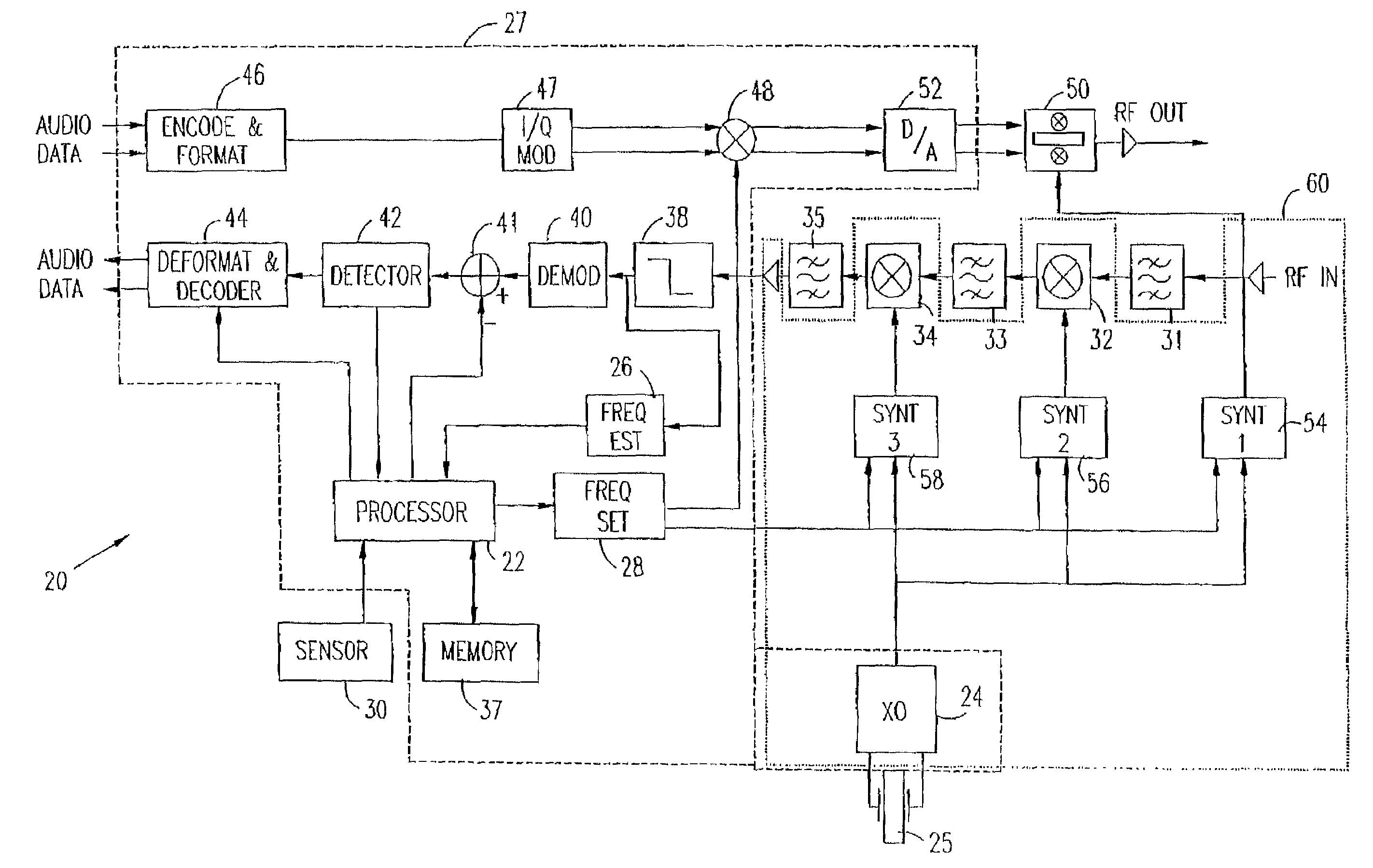
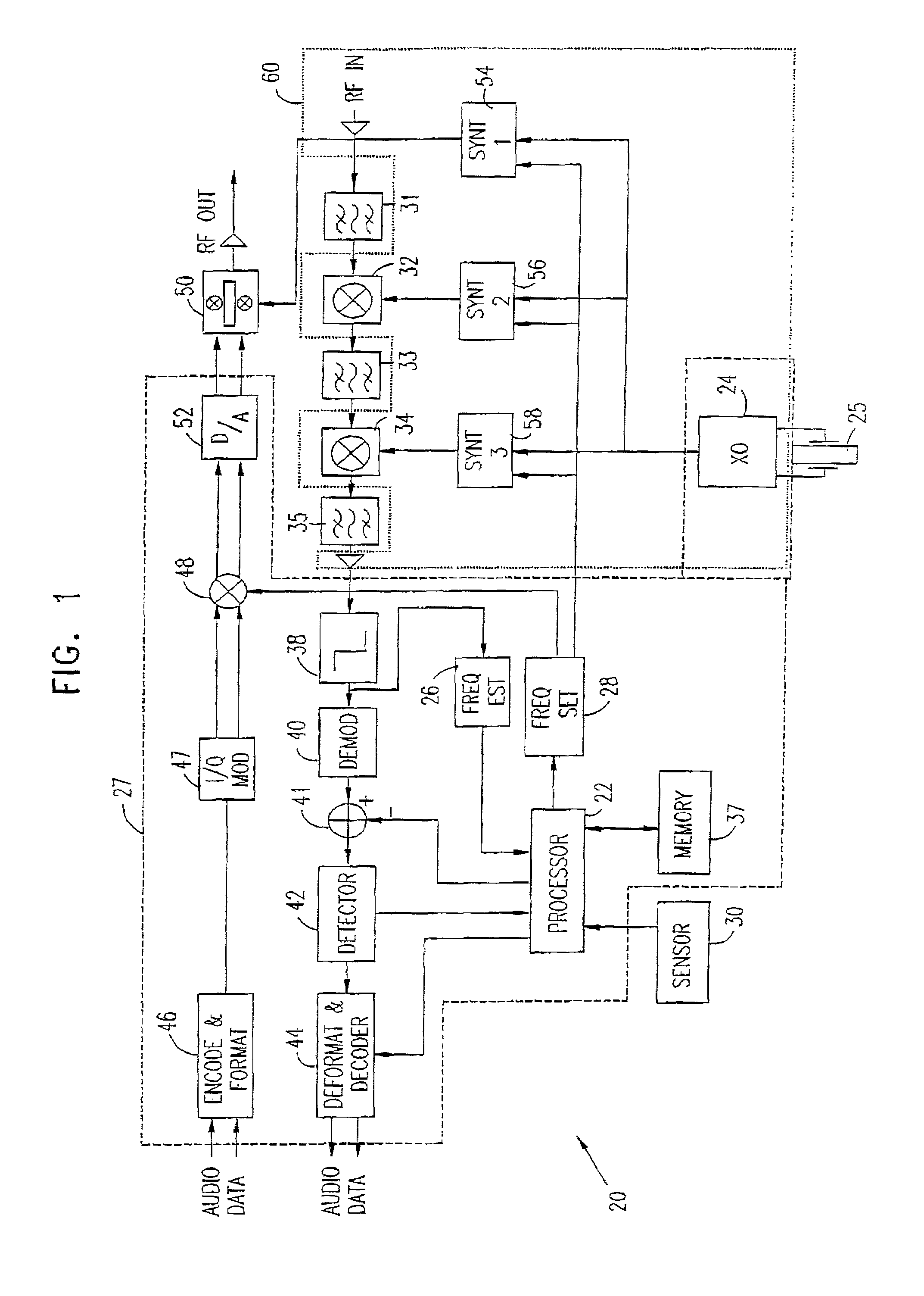
[0062]Reference is now made to FIG. 1, which is a schematic block diagram showing elements of a radio transceiver 20, in accordance with a preferred embodiment of the present invention. Transceiver 20 is of a type commonly used in PDC-standard cellular telephones, and is preferably implemented in the form of one or more custom integrated circuit devices, including all or most of the functions of the blocks shown in FIG. 1. 1t will be appreciated, however, that the principles of the present invention may similarly be applied to transceivers for use in accordance with other cellular communications standards, as well as transmitters, receivers and transceivers of other types.

[0063]Transceiver 20 preferably comprises a processor 22, which receives data from various elements of the transceiver and controls various transceiver functions. The processor preferably comprises a digital signal processor or microprocessor core, of any suitable type known in the art. For clarity and simplicity o...


PUM


Abstract

A radio communication device, which transmits or receives a signal at a predetermined carrier frequency. The device includes a reference oscillator, which generates a clock frequency having a clock frequency error relative to a specified frequency thereof, a processor, which estimates the clock frequency error and parses the error to determine coarse and fine error correction components, at least one frequency synthesizer, which responsive to the clock frequency and to the coarse error correction component, generates a partially corrected frequency having a residual frequency error, which partially corrected frequency is applied to process the signal and baseband processing circuitry, which applies the fine error correction component to process the signal so as to correct the residual frequency error.

Description

CROSS-REFERENCE TO PREVIOUS APPLICATIONS[0001]This application is a continuation of U.S. patent application Ser. No. 09 / 187,840 filed Nov. 6, 1998 now U.S. Pat. No. 6,400,930.FIELD OF THE INVENTION[0002]The present invention relates generally to radio communication devices, and specifically to devices and methods for accurate frequency control of radio transceivers.BACKGROUND OF THE INVENTION[0003]Radio transceivers used in mobile communication require stable clock sources and frequency synthesizers for use in modulation and demodulation of RF signals. The frequency synthesizers must be capable of tuning and locking onto a base station frequency with high accuracy. In a typical cellular communications system, for example, a radio transceiver must typically be capable of initial tuning, based on dead reckoning to an accuracy of 2 ppm, and then once a base station signal is detected, locking onto the signal frequency to an accuracy of 0.2 ppm. In the 800 MHz cellular baud, these requi...

Claims


Application Information

Patent Timeline
IPC IPC(8): H04B1/40H03J1/00H03J7/02H03L1/02
CPCH03J1/0008H03L1/026H03J7/02
Inventor BARAK, ILAN
Owner INTEL CORP
Learn More