Stacked adhesive optical sensor

a technology of optical sensors and adhesives, applied in the field of optical sensors, can solve problems such as adverse interference with measurement accuracy, and achieve the effect of prolonging the useful life of the produ

Inactive Publication Date: 2006-09-26
TYCO HEALTHCARE GRP LP
View PDF11 Cites 226 Cited by
  • Summary
  • Abstract
  • Description
  • Claims
  • Application Information

AI Technical Summary

Benefits of technology

[0009]The present invention provides an optical sensor having a cover layer, an emitter disposed on a first side of the cover, a detector disposed on the first side of said cover, and a plurality of stacked independent adhesive layers disposed on the same first side of the cover, wherein the top most exposed adhesive layer is attached to a patient's skin. Thus, when the sensor is removed to perform a site check of the tissue location, one of the adhesive layers may also be removed and discarded, exposing a fresh adhesive surface below for re-attachment to a patient's skin. The independent pieces of the adhesive layers can be serially used to extend the useful life of the product.

Problems solved by technology

The semi-rigid optical mount, by maintaining the separation relatively fixed reduces motion induced artifacts in the detected electro-optic signals, which may adversely interfere with measurement accuracy.

Method used


Image

  • Stacked adhesive optical sensor
  • Stacked adhesive optical sensor
  • Stacked adhesive optical sensor

Examples


Embodiment Construction

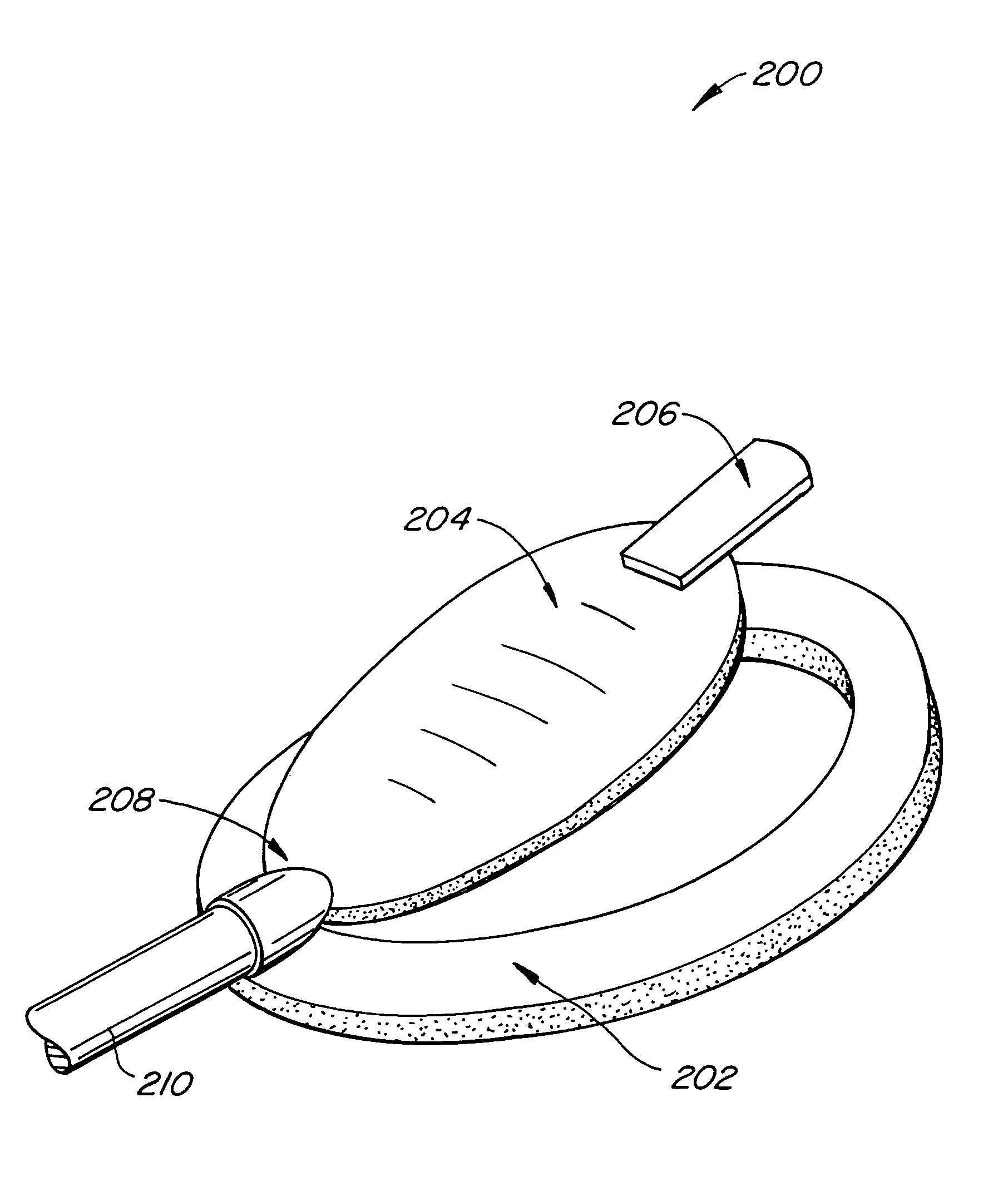
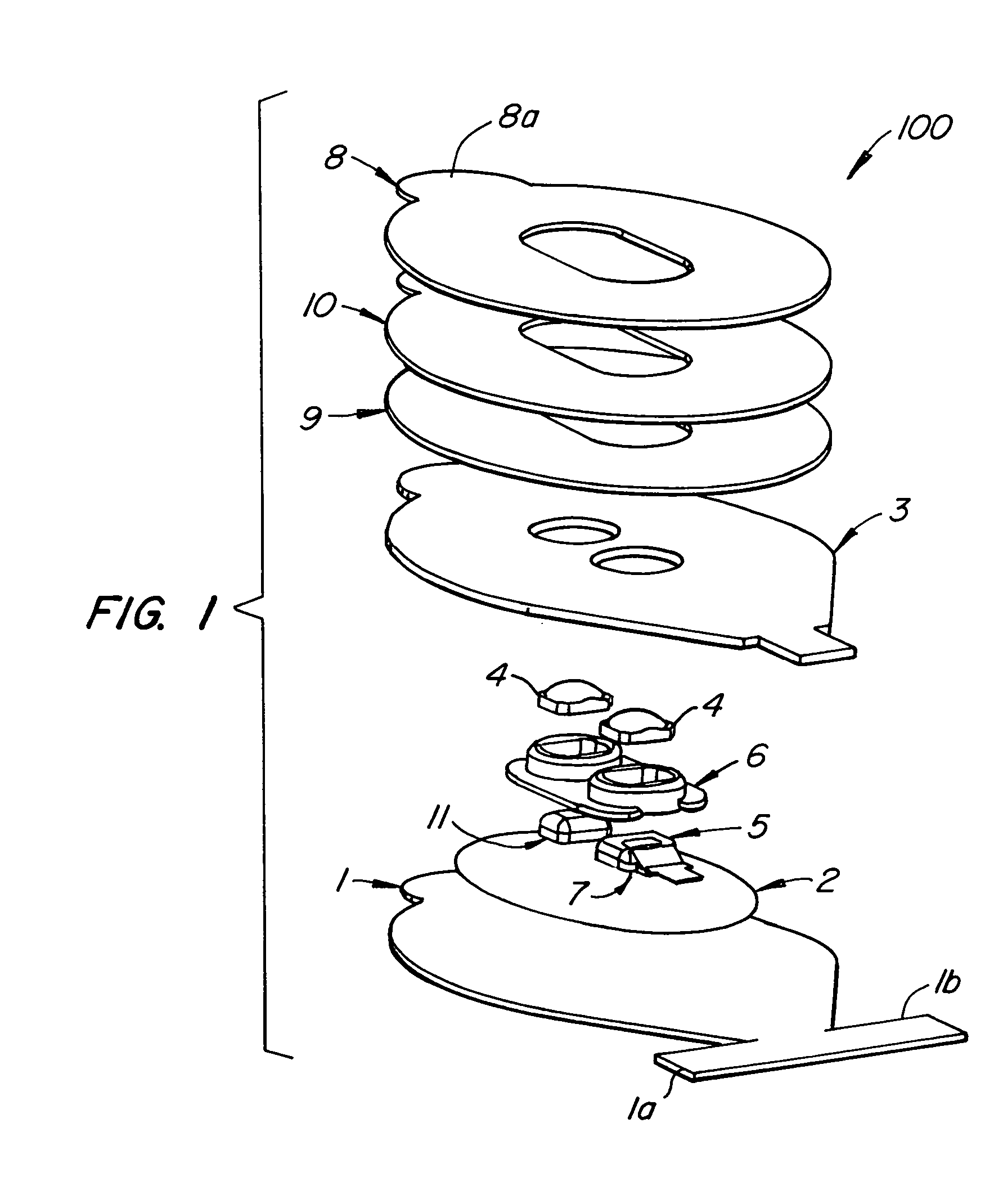
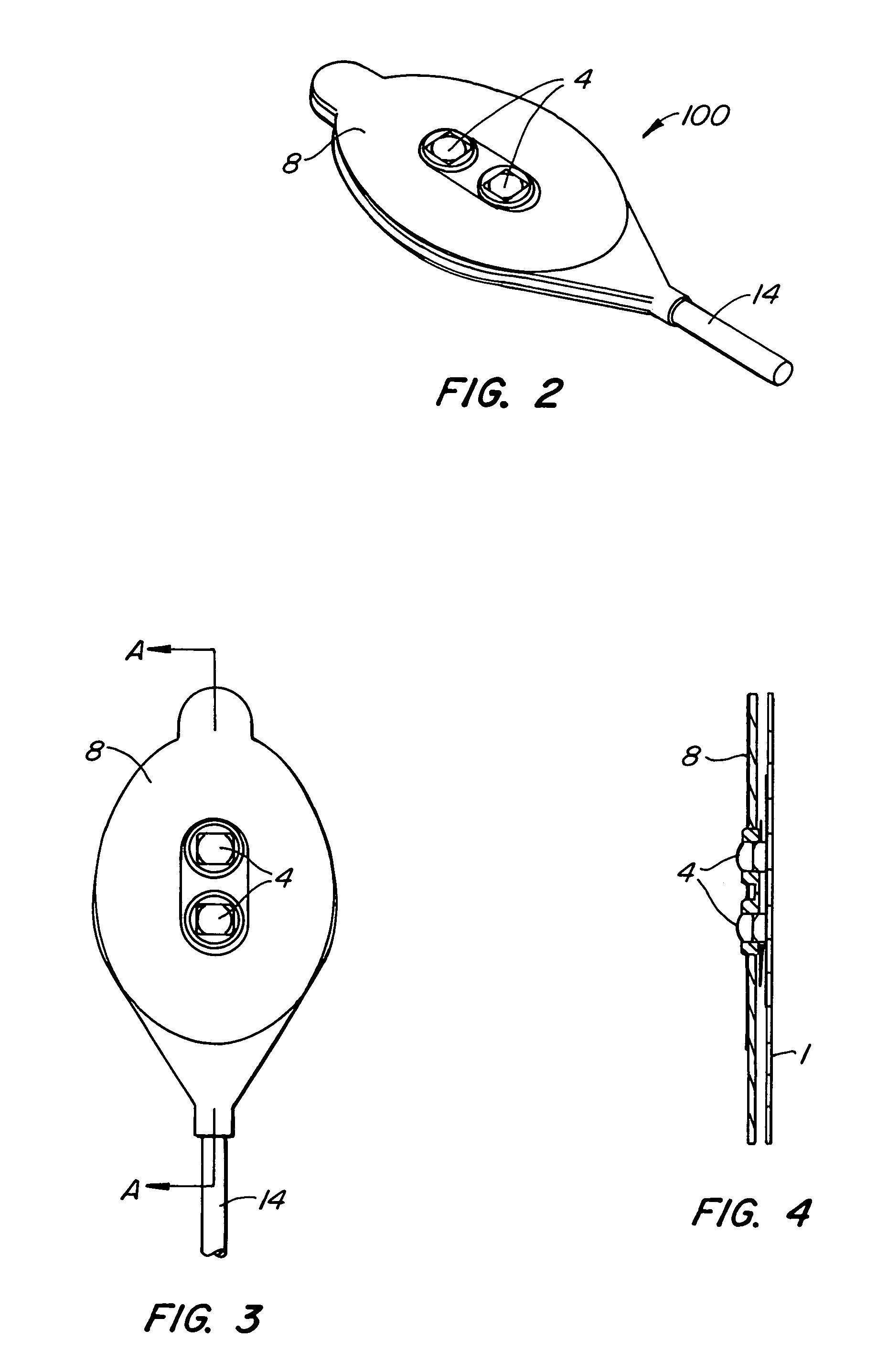
[0019]FIG. 1 is a perspective disassembled view of the sensor 100 according to an embodiment of the present invention. The sensor includes a sensor top 1 or cover layer which is exposed to the ambient environment when the sensor is attached to a patient's skin. In one embodiment, the cover layer 1 is fabricated of a common PVC foam. Alternately, the cover layer 1 is fabricated of a urethane foam material and particularly, an open cell breathable urethane foam such as, for example, the PORON™ family of urethanes commercially available from the Rogers corporation of Connecticut. A mask layer 2 preferably including a metalized plastic film is adhesively attached to the cover layer 1. In a preferred embodiment, the metalized masked layer 2 is an aluminized polypropylene film with a synthetic adhesive layer for attachment to the cover layer 1. The metalized mask layer 2 is so placed to prevent, minimize or reject secondary light from interfering with the photodetector 7. As used herein, ...


PUM

PropertyMeasurementUnit
thickaaaaaaaaaa
mechanicalaaaaaaaaaa
flexibleaaaaaaaaaa

Abstract

An optical sensor having a cover layer, an emitter disposed on a first side of the cover, a detector disposed on the first side of said cover, and a plurality of stacked independent adhesive layers disposed on the same first side of the cover, wherein the top most exposed adhesive layer is attached to a patient's skin. Thus, when the sensor is removed to perform a site check of the tissue location, one of the adhesive layers may also be removed and discarded, exposing a fresh adhesive surface below for re-attachment to a patient's skin. The independent pieces of the adhesive layers can be serially used to extend the useful life of the product.

Description

CROSS-REFERENCE TO RELATED APPLICATION[0001]The present application claims priority to U.S. Provisional Patent Application No. 60 / 328,924, filed Oct. 12, 2001, the teachings of which are incorporated herein by reference for all purposes.BACKGROUND OF THE INVENTION[0002]The present invention relates to optical sensors, and in particular to pulse oximeter sensors.[0003]Many types of optical sensors are used to measure physiological characteristics of a patient. Typically, an optical sensor provides emitted light which is then scattered through a portion of a patient's tissue and detected. Various characteristics of a patient can be determined from analyzing such light, such as oxygen saturation, pulse rate, tissue bilirubin, etc.[0004]Pulse oximetry is typically used to measure various blood flow characteristics including, but not limited to, the blood-oxygen saturation of hemoglobin in arterial blood, the volume of individual blood pulsations supplying the tissue, and the rate of blo...

Claims


Application Information

Patent Timeline
Patent Type & Authority Patents(United States)
IPC IPC(8): A61B5/00G01N21/17A61B5/024A61B5/145A61B5/1455
CPCA61B5/6814A61B5/6819A61B5/6826A61B5/6829A61B5/6833A61B5/6838A61B5/6841A61B5/0205A61B5/14551A61B5/6832A61B5/14552A61B5/02427Y10T29/49826A61B2562/0233A61B2562/043A61B2562/146A61B2562/164G01N21/49G01N2021/3144A61B5/68335
Inventor O'NEIL, MICHAEL PATRICKMANNHEIMER, PAULCHIN, RODNEYMERCHANT, ADNANCOAKLEY, JOSEPHHANNULA, DON
Owner TYCO HEALTHCARE GRP LP
Why Eureka
Try Eureka