
Efficient quantum computing operations

a quantum computing and efficient technology, applied in computing models, instruments, nanoinformatics, etc., can solve the problems of no longer secure current cryptography systems, large inputs are generally computationally time-consuming, and computation problems are only efficiently solved for small inputs, etc., to achieve and efficient performance of q

Inactive Publication Date: 2006-09-26
MAGIQ TECH INC
View PDF38 Cites 37 Cited by
  • Summary
  • Abstract
  • Description
  • Claims
  • Application Information

AI Technical Summary

Benefits of technology

[0028]It is another object of the invention to provide systems and methods for efficiently performing QFT.
[0029]It is another object of the invention to provide systems and methods for efficiently performing QFT for state spaces of dimension 2n.
[0030]It is another object of the invention to provide systems and methods for efficiently performing QFT for state spaces of arbitrary dimension.
[0038]One example of a qubit includes spin ½ nuclei and equipment designed to generate nuclear magnetic resonance in the nuclei to change and measure the spin state of the nuclei. A more specific example is an organic molecule that provide different local fields at different molecular Carbon nuclei sites in the molecule. The nuclear moment of C13 is sensitive to local fields. Fabricating such an organic molecule with the isotope C13 in different molecular carbon sites in the molecule provides different resonance frequencies for nuclear magnetically resonating the C13 nuclei, depending upon the molecular position of the C13 atoms, thereby enabling the different sites to be used as a distinct qubits.

Problems solved by technology

If a function that expresses the size of a circuit for computing a specified computation grows very quickly as the input size increases then that computation problem is only efficiently solvable for small inputs.
A problem implementing quantum circuits is data loss due to interaction of qubits with particles in the environment causing changes in the qubit's quantum mechanical state.
Current RSA cryptography systems make use of the assumption that factoring large numbers is generally a computationally time intensive task for large integers.
Therefore, current cryptography systems are no longer secure.

Method used


Image

  • Efficient quantum computing operations
  • Efficient quantum computing operations
  • Efficient quantum computing operations

Examples


Embodiment Construction

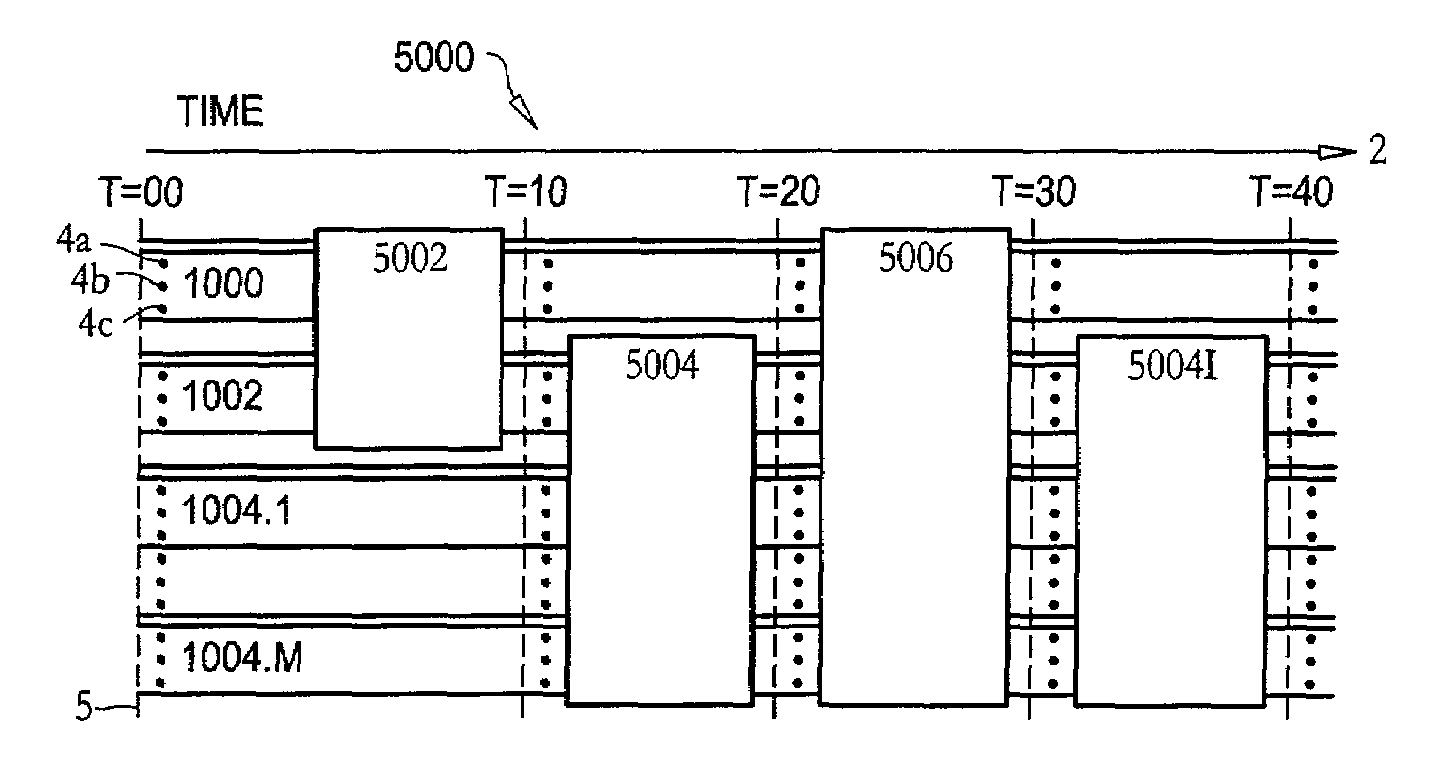
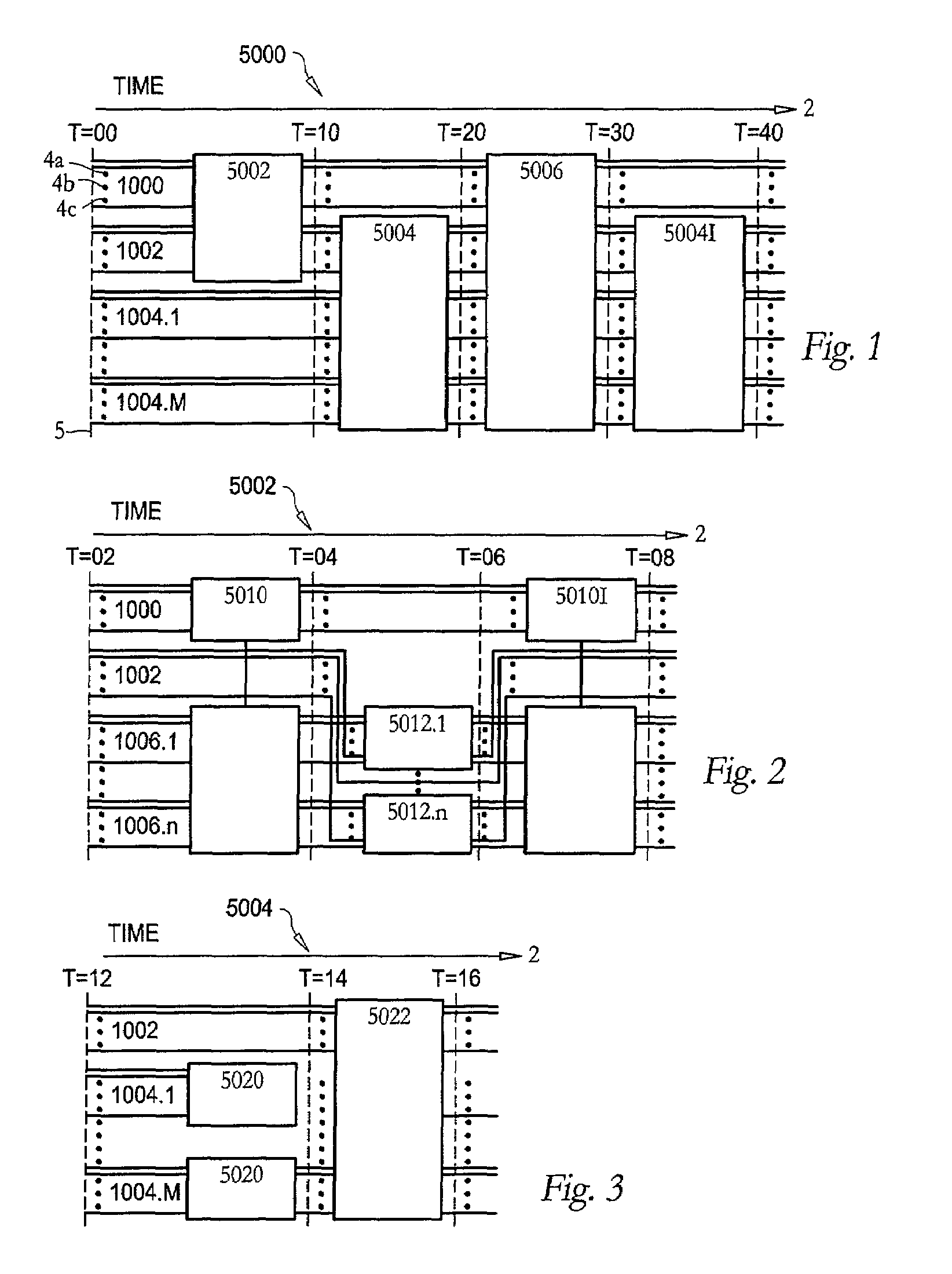
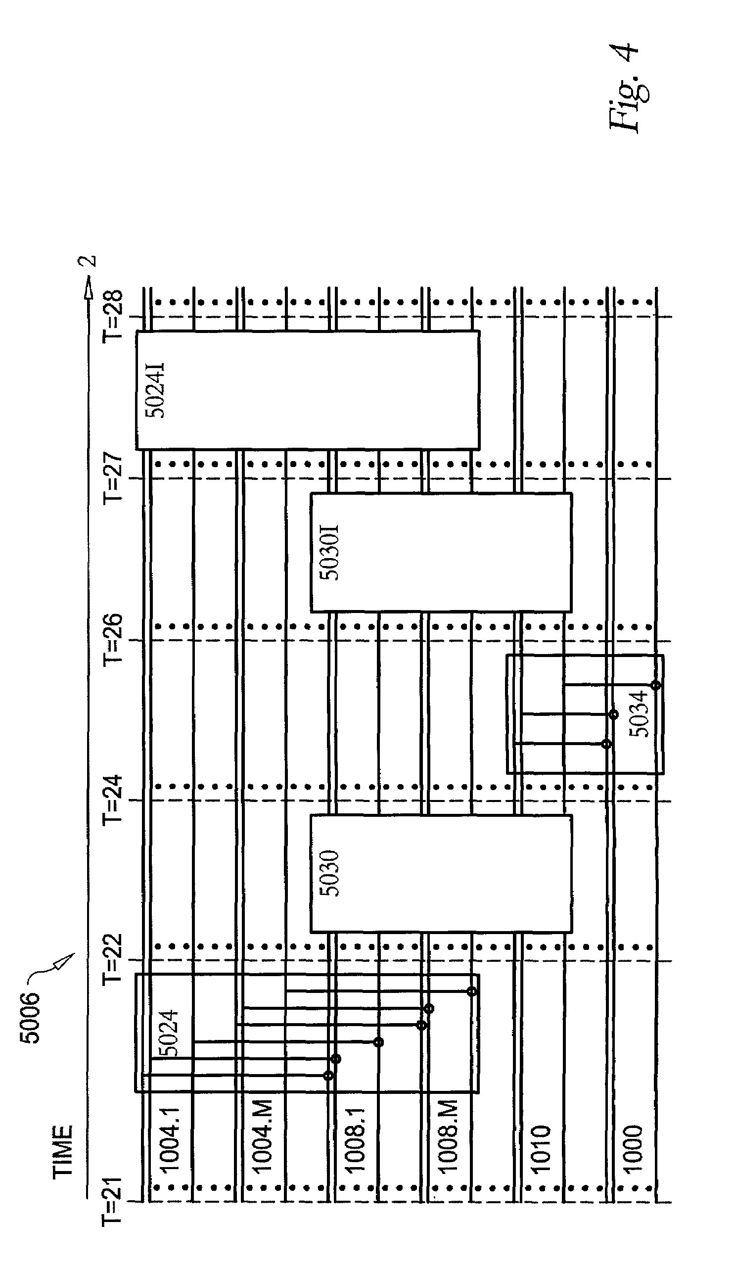
[0054]FIGS. 1–7 represent time evolution of qubits in a physical system forming the data processing unit of a quantum computer. In FIGS. 1–7, time increases from left to right. In FIGS. 1–7, each horizontal line represents the information content of the spin states of a spin ½ particle, a qubit of the data processing unit. Rectangles represent physical operations performed on the qubits whose lines intersect the rectangle. In FIGS. 1–7, numbers in the range 0–40 label sequential times. In FIGS. 1–7, numbers in the range 1000 to 1010 label sets of approximately equal numbers, n, of qubits. In FIGS. 1–7, numbers in the range 5000–5032 label rectangles representing physical operations on qubits. Numbers representing inverses of a physical operation have an “I” suffix. An inverse of a quantum operation requires the same depth and size as the operation. Modulus 2n herein refers indirectly to the fact that there are 2n basis states necessary to describe the state of n spin ½ particles

[005...


PUM


Abstract

A method of performing a quantum Fourier transform in a quantum computing circuit is disclosed. The method includes forming a quantum computing circuit as a collection of two-qubit gates operating on a sequence of input qubits. Auxiliary qubits are then interacted with the original input qubits to place the auxiliary qubits in a state corresponding to an output of a discrete Fourier transform of a classical state of the input qubits. The original input qubits are then re-set to their ground state by physically interacting the input qubits with the auxiliary qubits. The auxiliary qubits are then transformed to a state representative of a quantum Fourier transform of the sequence of input qubits.

Description

CROSS-REFERENCE TO RELATED APPLICATIONS[0001]This application claims priority under 35 USC 119(e) to U.S. provisional application Ser. No. 60 / 294,089, filed May 29, 2001.BACKGROUND OF THE INVENTION[0002]1. Field of the Invention[0003]The present invention relates to the field of computing and more particularly to quantum computing.[0004]2. Description of the Background[0005]In electronic circuits a gate is a digital logic operation embodied in a circuit having at least one digital input, or bit, and having one digital output, or bit, wherein the circuit generates a value of the output that depends upon the values of the inputs. The gate references the manipulation of the input bits to generate the value of the output bit. Measures of circuit efficiencies include speed of performing their operation and number of gates required to perform their operation.[0006]The input size of a circuit means the number of bits that are in the input. The most common circuit input measurements are the...

Claims


Application Information

Patent Timeline
IPC IPC(8): G06F15/00H01L29/06G06N99/00
CPCG06N99/002B82Y10/00G06N10/00
Inventor CLEVE, RICHARDWATROUS, JOHN
Owner MAGIQ TECH INC
Learn More