Proactive on-line diagnostics in a manageable network

a network and network management technology, applied in the field of communication network fault diagnosis methods and systems, can solve the problems of increasing diagnostic system burden, increasing complexity of computer network, and increasing levels of reliability, availability and service required of these networks, so as to achieve the effect of not incurring prohibitive computational costs and memory requirements

Inactive Publication Date: 2006-09-26
LINKEDIN
View PDF8 Cites 146 Cited by
  • Summary
  • Abstract
  • Description
  • Claims
  • Application Information

AI Technical Summary

Benefits of technology

[0011]Thus, unlike model-based diagnostic methods known in the art, preferred embodiments of the present invention use dynamic Bayesian Network models, which are built specifically in response to each alarm or group of alarms that is received. Consequently, these models completely and accurately reflect the actual, current network conditions, without incurring the prohibitive computational costs and memory requirements of maintaining a complete model of the entire network. Any given model ...

Problems solved by technology

The complexity of computer networks continues to grow, and the levels of reliability, availability and service required of these networks continue to rise, as well.
These factors place an increasing burden on diagnostic systems that are used in computer networks to identify and isolate network faults.
Analyzing this information to identify network faults is beyond the capabilities of all but the most skilled network administrators.
As a result, the rules themselves are difficult to devise and cannot be applied generally to all error conditions that may arise.
Such rules are not globally applicable and must generally be updated when the system configuration is changed.
Switched computing and communication networks, such as System Area Networks (SANs), pose particular challenges for diagnostic applications in terms of their complexity and inherent uncertainties.
The...

Method used


Image

  • Proactive on-line diagnostics in a manageable network
  • Proactive on-line diagnostics in a manageable network
  • Proactive on-line diagnostics in a manageable network

Examples


Embodiment Construction

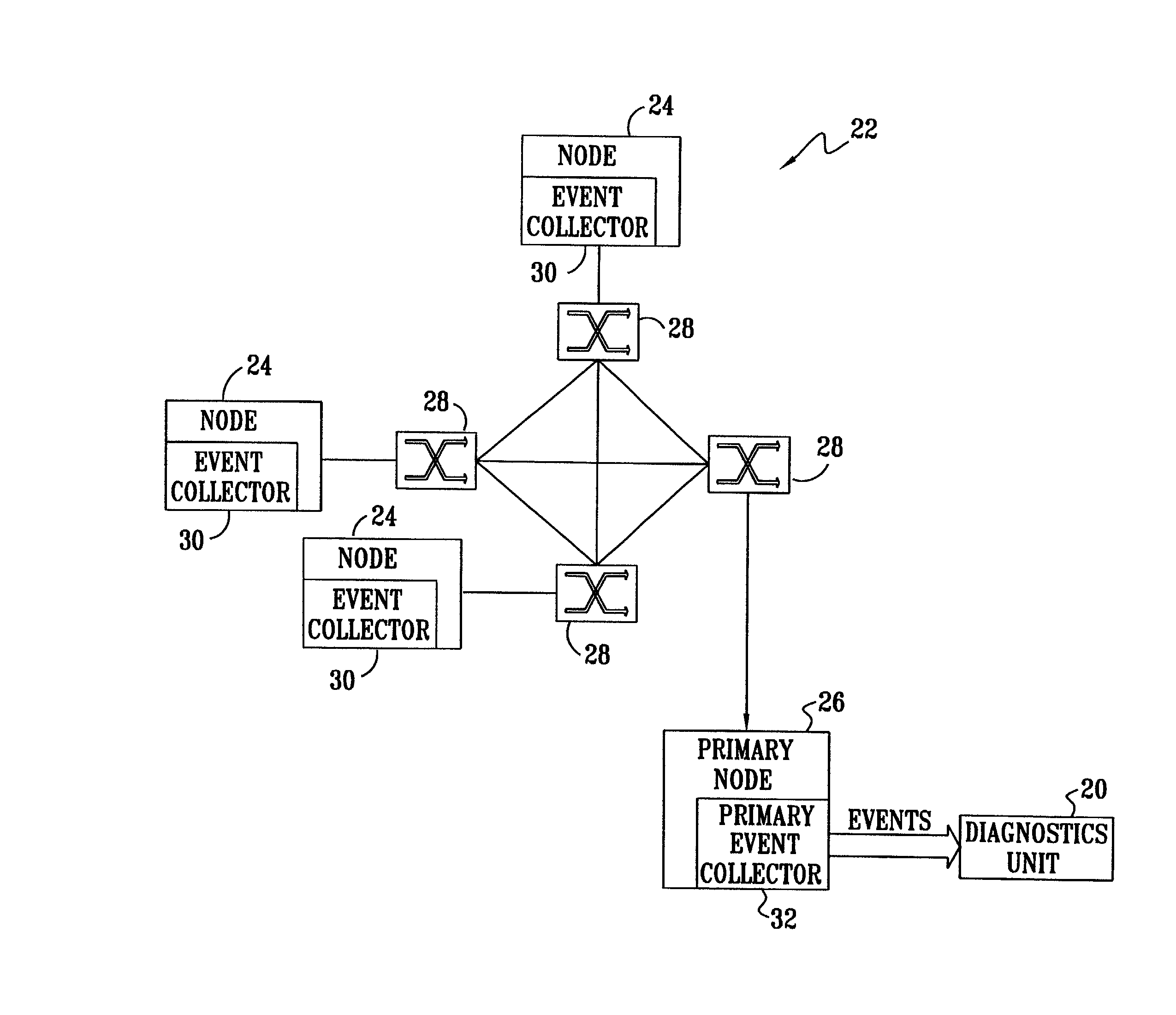
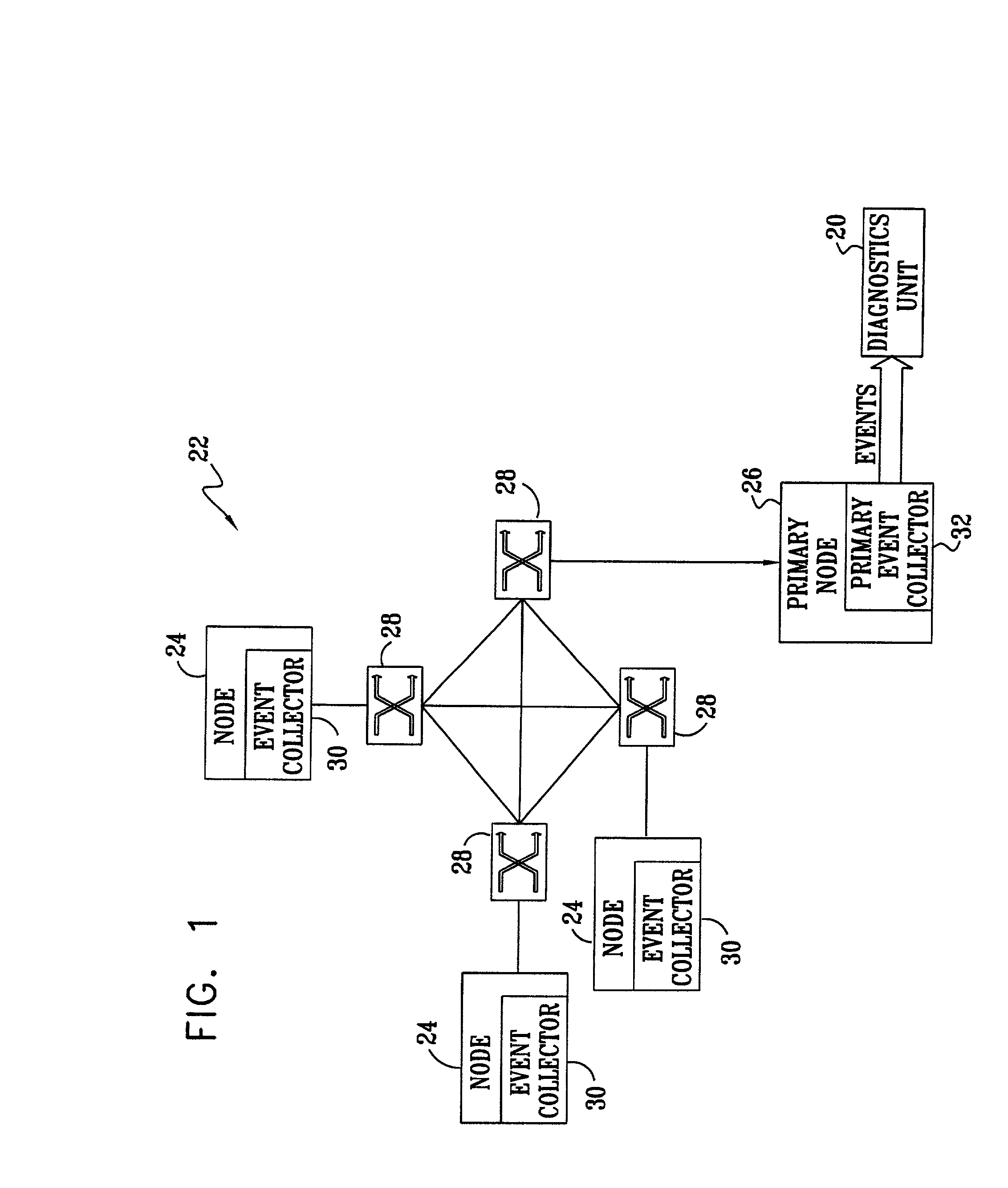
[0047]FIG. 1 is a block diagram that schematically illustrates a manageable communication network 22 and a diagnostic unit 20 used to monitor the network, in accordance with a preferred embodiment of the present invention. Network 22 typically comprises a system / storage area network (SAN), as is known in the art. In such a network, nodes 24 may comprise servers or other computer processors, input / output (I / O) devices, storage devices or gateways, which are interconnected by switches 28. An example of such a network is the RS / 6000 SP system produced by IBM Corporation, of Armonk, N.Y. Network 22 is termed “manageable” in the sense that it provides two key features exploited by diagnostic unit 20: First, the network is monitored for errors and failures, such as packet corruption or devices not responding, and for statistics that may reflect abnormal functionality. Second, the network is configurable, particularly in terms of the ability of a system operator or automatic controller to ...


PUM


Abstract

A method for diagnosis of a system made up of a plurality of interlinked modules includes receiving an alarm from the system indicative of a fault in one of the modules. Responsive to the alarm, a causal network is constructed associating the fault with malfunctions in one or more of the modules that may have led to the fault and relating a conditional probability of the fault to respective probabilities of the malfunctions. Based on the alarm and the causal network, at least one of the probabilities of the malfunctions is updated. A diagnosis of the alarm is proposed responsive to the updated probabilities.

Description

CROSS-REFERENCE TO RELATED APPLICATIONS[0001]This application claims the benefit of U.S. Provisional Patent Application No. 60 / 214,971, filed Jun. 29, 2000, which is incorporated herein by reference.FIELD OF THE INVENTION[0002]The present invention relates generally to methods and systems for fault diagnosis in communication networks, and specifically to methods for identifying faulty components in such networks while normal communication activity is going on.BACKGROUND OF THE INVENTION[0003]The complexity of computer networks continues to grow, and the levels of reliability, availability and service required of these networks continue to rise, as well. These factors place an increasing burden on diagnostic systems that are used in computer networks to identify and isolate network faults. In order to avoid failures that may severely interfere with network activity, it is important to detect intermittent and sporadic problems that are predictive of incipient failures and to pinpoint ...

Claims


Application Information

Patent Timeline
IPC IPC(8): G06F15/173H04L12/24
CPCH04L41/142H04L41/0681
Inventor CHIRASHNYA, IGORSHALEV, LEAHSHOIKHET, KIRILL
Owner LINKEDIN
Why Eureka
Try Eureka