Vibration attenuator clip and attenuator using the same

Inactive Publication Date: 2006-10-03
BONITA IP
View PDF11 Cites 5 Cited by
  • Summary
  • Abstract
  • Description
  • Claims
  • Application Information

AI Technical Summary

Benefits of technology

[0005]The present invention relates to a clip designed to be used with a vibration attenuator for a brake disk lathe used to periodically resurface a pair of disk surfaces of a brake disk. The clip is designed to be used with a vibration attenuator designed for use with a brake disk lathe having a pair of cutting tools, each of which is mount

Problems solved by technology

One limitation of this technique is that the pads wear as they rotate against the disk surfaces, and thus their effectiveness in attenuating vibrations diminishes as a function of time, since the spring force will diminish as the pads wear.
This problem compounds as the thickness of the friction pads increases, since employing a spring which provides sufficient pressure at or near the time when the

Method used


Image

  • Vibration attenuator clip and attenuator using the same
  • Vibration attenuator clip and attenuator using the same
  • Vibration attenuator clip and attenuator using the same

Examples


Embodiment Construction

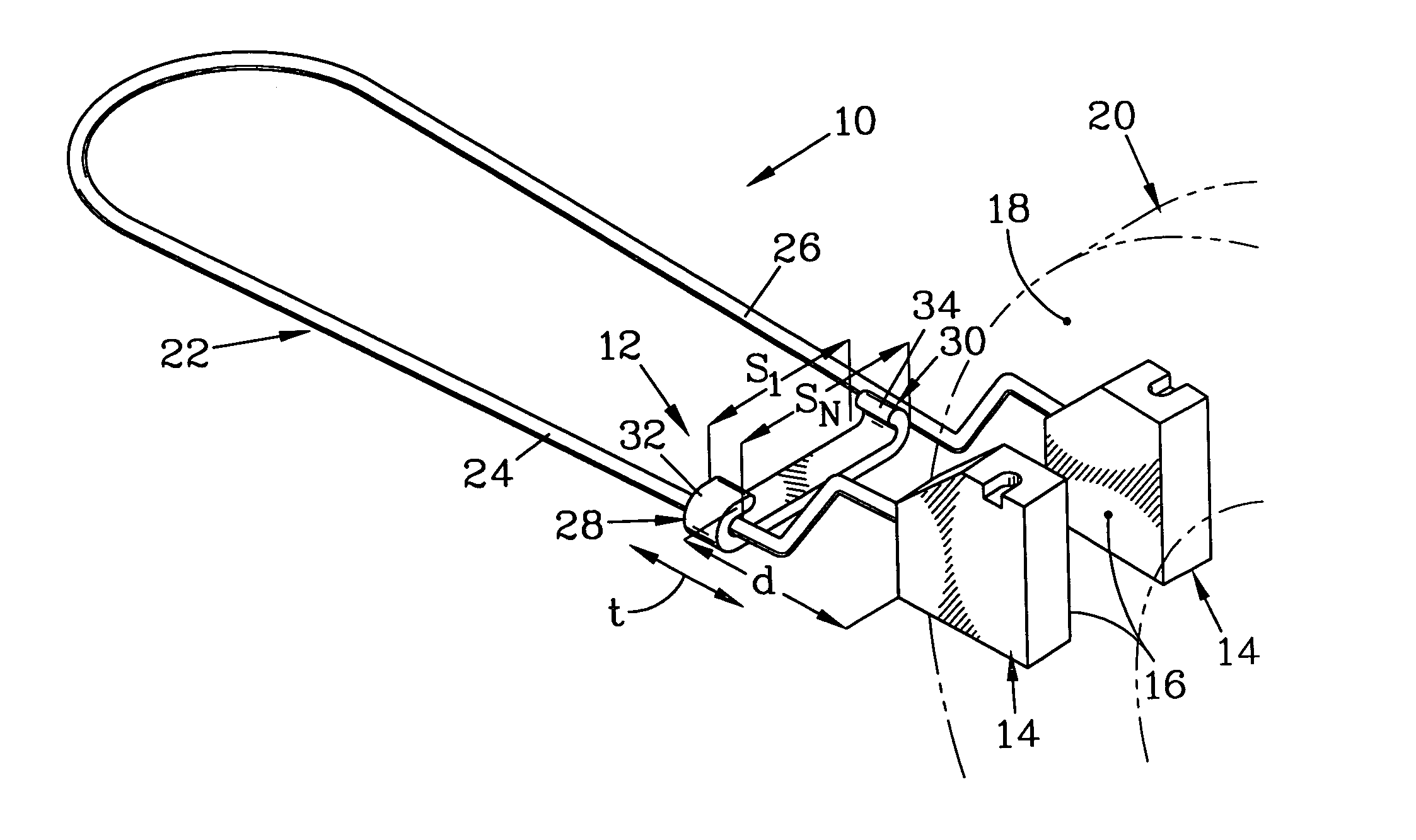
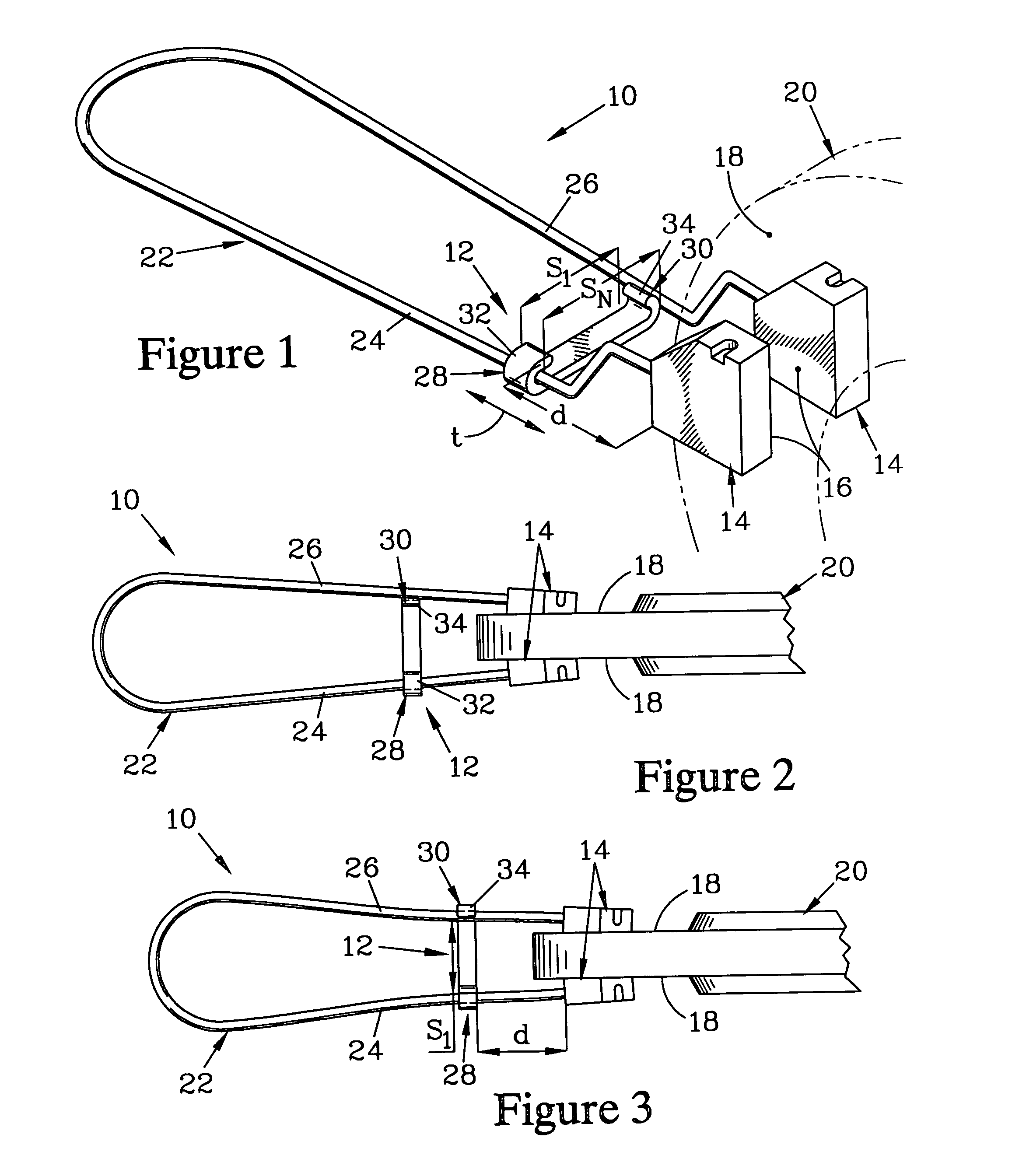
[0026]FIGS. 1 through 3 are views of a vibration attenuator 10 that is suitable for use with a clip 12 which forms one embodiment of the present invention and which, when used in combination with the attenuator, provides an improved attenuator system. These figures show the vibration attenuator 10 in an inverted position to better show the structure; this convention is also followed in the figures illustrating the other embodiments discussed below (a figure showing such a vibration attenuator in the service position on a brake lathe is found in U.S. Pat. No. 6,591,720). FIG. 1 is an isometric view of the vibration attenuator 10 and the clip 12, while FIGS. 2 and 3 are plan views showing the vibration attenuator 10 when in service. The vibration attenuator 10 has a pair of friction pads 14 which each have a disk-engaging surface 16. When the vibration attenuator 10 is in service, the disk-engaging surfaces 16 engage caliper-engaging surfaces 18 of a brake disk 20, as shown in FIGS. 2...


PUM

PropertyMeasurementUnit
Thicknessaaaaaaaaaa
Forceaaaaaaaaaa
Separationaaaaaaaaaa

Abstract

A clip engages a pair of legs of a vibration attenuator to reduce the local separation of the legs, thereby increasing the force of friction pads, affixed to the legs, against a brake disk to compensate for reduced thickness of the friction pads due to wear. The clip has a first end region, which can preferably be snappably engaged with one of the legs so as to pivot thereabout. The clip has a second end region with a protrusion which can be engaged with the other leg so as to restrain it at the reduced separation. Preferably, a second protrusion is provided to allow restraining the other leg at an even smaller local separation from the leg that is rotatably engaged by the first end region. A tab preferably extends beyond the first protrusion to aid in engaging and disengaging the second end region from the other leg.

Description

FIELD OF INVENTION[0001]The present invention is for a vibration attenuator for use with a disk brake lathe to reduce noise and vibrations resulting from machining the surfaces of a brake disk by the lathe. More particularly, it relates to a clip for a vibration attenuator that allows the attenuator pressure applied to the brake disk to be adjusted to compensate for wear of the attenuator and, in some situations, the condition of the disk brake surface.BACKGROUND OF THE INVENTION[0002]Automotive brake disks are periodically resurfaced by a disk brake lathe in order to maintain proper operation of the brakes in service. The disk brake lathe typically has a pair of cutting tools, each attached to a tool holder by a fastener to allow replacement when the cutting tool becomes worn. The tool holders position the cutting tools against the surfaces of the brake disk to establish a desired depth of cut, and then maintain the cutting tools in position as they are drawn across the disk surfac...

Claims


Application Information

Patent Timeline
IPC IPC(8): B23B3/06
CPCB23B5/02F16F15/02F16F15/022B23B2250/16Y10T74/2132Y10S82/904Y10T82/21Y10T82/2595
Inventor OPPERMANN, HARALD
Owner BONITA IP
Why Eureka
Try Eureka