
Torque limiting device for hydraulic piston pump

a technology of torque limiting device and hydraulic piston pump, which is applied in the direction of pump parameter, positive displacement liquid engine, machine/engine, etc., can solve the problems etc., and achieves the effect of limiting the torque required by the pump, reducing displacement, and limiting displacement reduction

Inactive Publication Date: 2006-10-03
SAUER DANFOSS NORDBERG
View PDF12 Cites 6 Cited by
  • Summary
  • Abstract
  • Description
  • Claims
  • Application Information

AI Technical Summary

Benefits of technology

[0010]A torque control for a hydrostatic piston pump having a cylinder block and a swashplate disposed within a housing. The control comprises a servo piston rod that is connected to a servo piston that is within a first cavity that receives compensation pressure. The compensation pressure comes from a compensator pressure conduit that pumps pressure into the first cavity to urge the servo piston toward the swashplate. The servo piston is designed to have a head on its first end and a stem that is sealingly inserted within a bore. Contacting the stem of the servo piston within the bore is the stem of a maximum displacement piston that has a head within a second cavity. Within the second cavity is a system pressure conduit which supplies system pressure to the maximum displacement piston to urge it towards the swashplate. The maximum displacement of the maximum displacement piston towards the swashplate is controlled by a spring stopping element within the second cavity that limits the amount of travel the maximum displacement piston can move toward the swashplate, thus limiting the displacement reduction. As system pressure builds, the maximum displacement piston begins to compress the Bellville washer set until it reaches solid length. This results in a reduced displacement at high pressure, thus limiting the torque required by the pump.

Problems solved by technology

This results in a reduced displacement at high pressure, thus limiting the torque required by the pump.

Method used


Image

  • Torque limiting device for hydraulic piston pump
  • Torque limiting device for hydraulic piston pump
  • Torque limiting device for hydraulic piston pump

Examples


Embodiment Construction

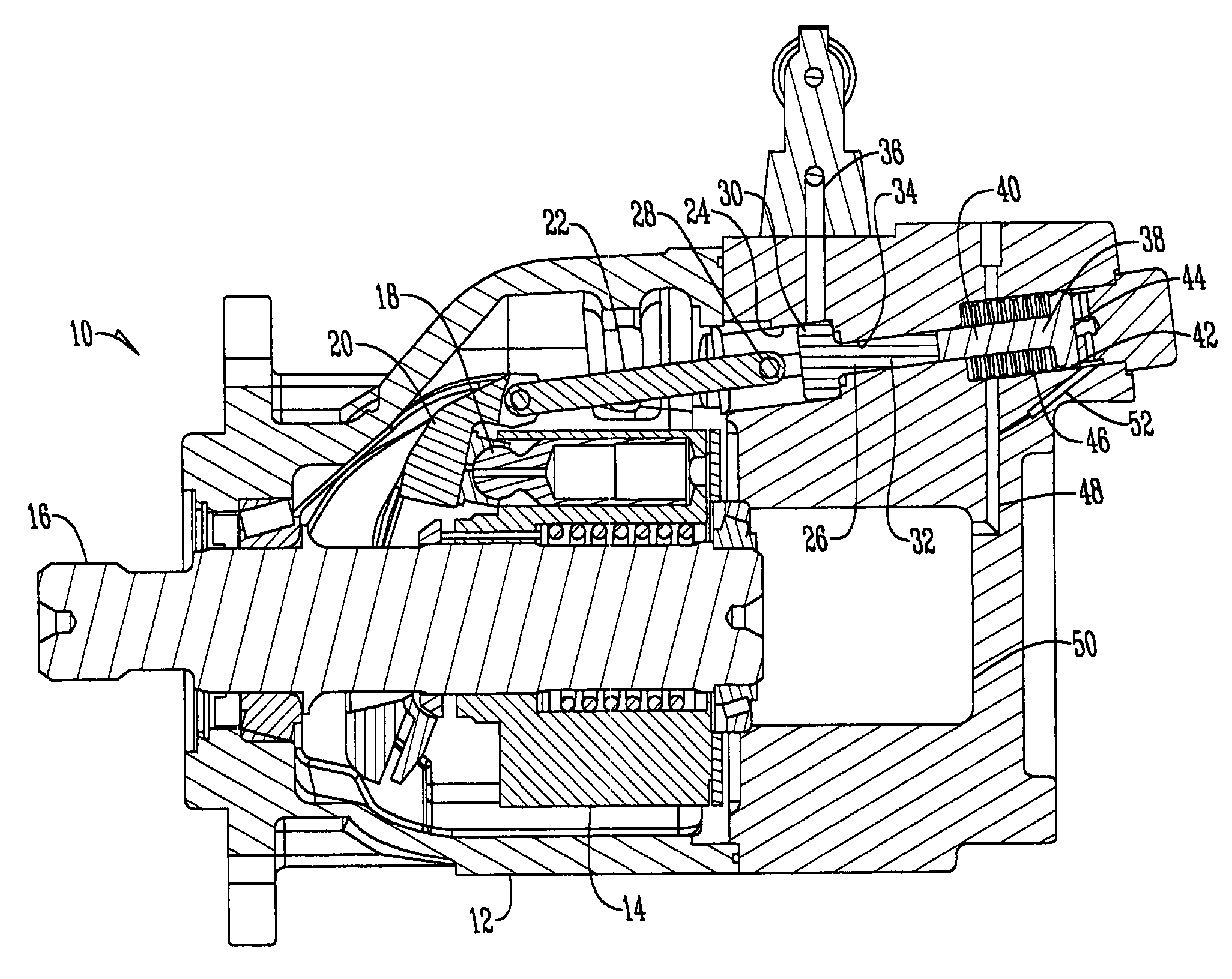
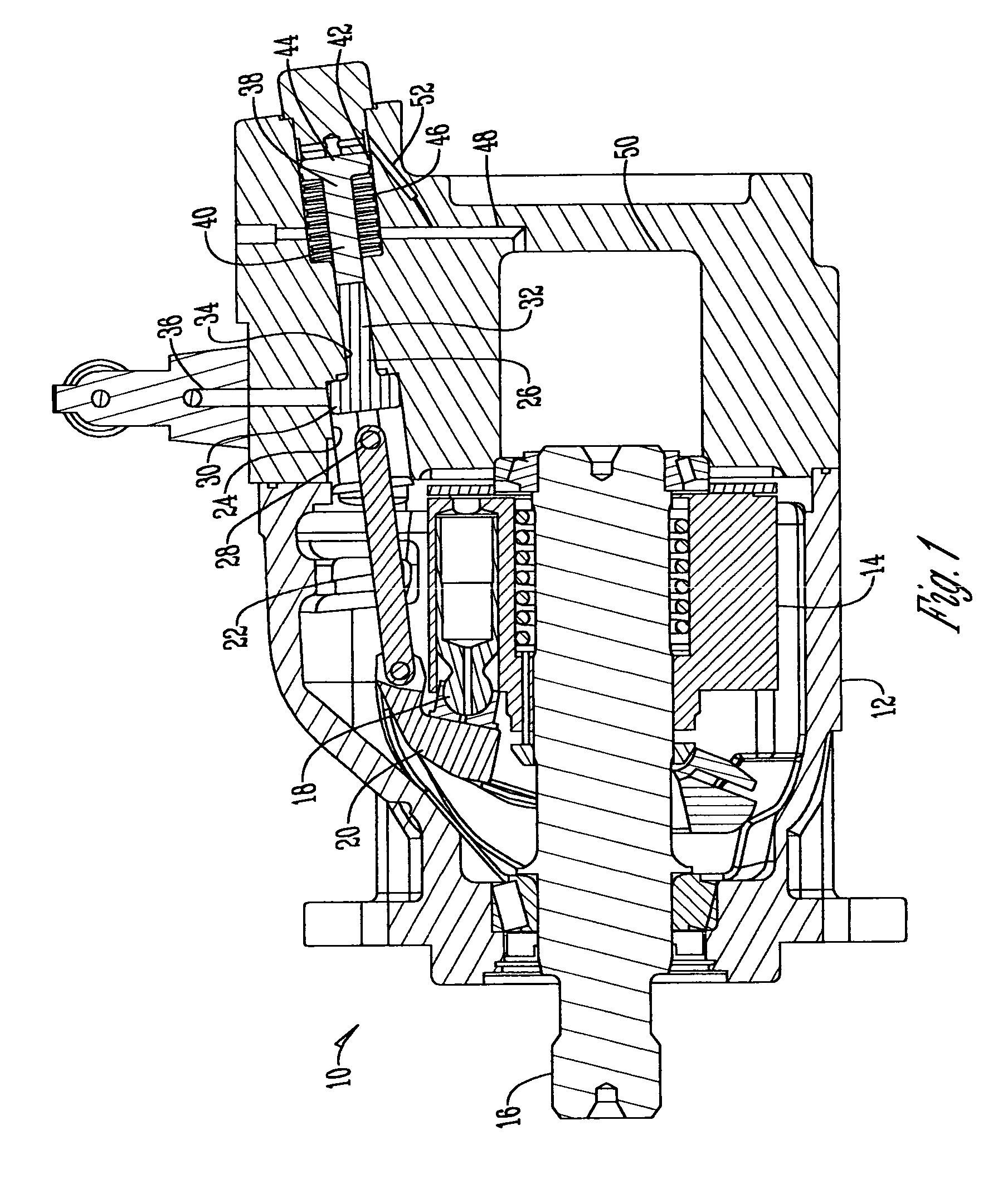
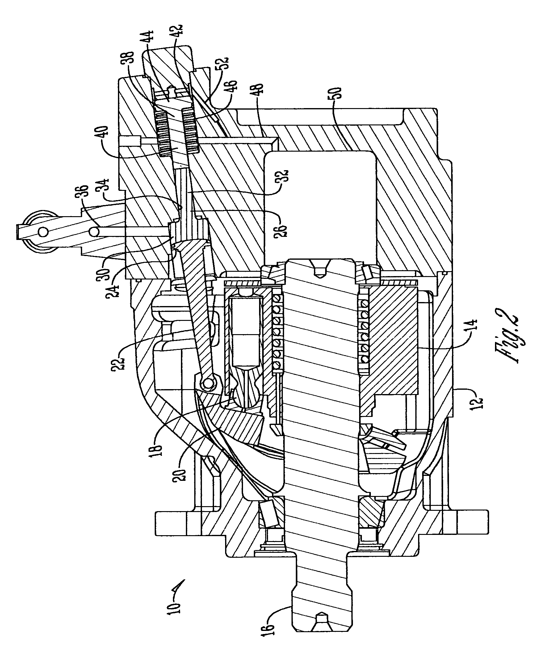
[0013]FIGS. 1–2 show a hydrostatic piston pump 10. The hydrostatic piston pump 10 has a housing 12 that contains a cylinder block 14 that is connected and rotates with shaft 16. A series of pistons 18 in the cylinder block 14 rests against a swashplate 20 that controls the operation of the piston pump.

[0014]The torque control of the hydrostatic piston pump 10 comprises a servo piston rod 22 that is operably connected to the swashplate 20 and is disposed within a first cavity 24. Connected within the first cavity 24 to the servo piston rod is a servo piston 26. One skilled in the art will appreciate that the servo piston rod 24 and servo piston 26 may be connected by a pin joint connection 28, or as an alternative, as seen in FIG. 2 by a sliding / butt joint. The servo piston 26 has a head 30 disposed within the first cavity 24 and a stem 32 that is disposed within a bore 34. The stem 32 is of size and shape to completely seal the bore 34 to ensure that no pressure from the cavity 24 i...


PUM


Abstract

A torque control for a hydrostatic piston pump that provides for a servo piston rod that is connected to the swashplate of the pump and connected to a servo piston within a first cavity that receives compensation pressure that urges the servo piston toward the swashplate. The servo piston has a stem that extends into a bore and is in contact with the stem of a maximum displacement piston that extends into a second cavity that is acted upon by system pressure to urge the maximum displacement piston toward the swashplate. Additionally, within the second cavity is a set of Bellville washers that surround the stem of the maximum displacement piston to limit the movement of the maximum displacement piston toward the swashplate.

Description

BACKGROUND OF THE INVENTION[0001]This invention relates to an improved hydraulic pump that is able to limit the amount of torque produced within the pump. More specifically and without limitation, this invention relates to a torque limiting system within a hydraulic piston pump.[0002]The pressure compensated hydraulic piston pump is widely used in industry as a means of driving a wide range of hydraulic devices. The pressure compensated pump delivers a fixed maximum volume of fluid at pressures below the design level and then an abrupt cutoff of the flow as the design pressure level is reached. Such pumps are usually equipped with a variable pressure control which allows the cutoff pressure to be easily adjusted. The operation of the pump can be ascribed as follows: the pump is driven by an external power source through a shaft. A cylinder block is connected to and rotates with the shaft. A series of pistons in the cylinder block rotate with the block and rests against the side of a...

Claims


Application Information

Patent Timeline
IPC IPC(8): F01B3/02F01B31/04
CPCF04B1/324F04B49/08F04B2201/1202
Inventor BOONE, NICK LLINGENFELTER, GARY R
Owner SAUER DANFOSS NORDBERG
Features
  • Generate Ideas
  • Intellectual Property
  • Life Sciences
  • Materials
  • Tech Scout
  • Unparalleled Data Quality
  • Higher Quality Content
  • 60% Fewer Hallucinations
Learn More