Drill insert geometry having V-notched web

a drill insert and geometry technology, applied in the field of cutting tool inserts, can solve the problems of deformation of the workpiece, increased heat produced at the drill insert point, and the point or tip of the drill insert is not efficient cut into the workpiece, so as to reduce the heat generated at the insert tip, enhance the self-centering capability, and improve the stability and feed rate

Inactive Publication Date: 2006-10-03
ALLIED MASCH & ENG CORP
View PDF36 Cites 8 Cited by
  • Summary
  • Abstract
  • Description
  • Claims
  • Application Information

AI Technical Summary

Benefits of technology

[0005]The present invention provides a novel drill insert having a V-notched web. The V-notched web allows greater stability and feed rates, while decreasing the heat generated at the insert tip. The stability of the V-notch can further enhance the self-centering capability of existing self-centering configurations of drill inserts. These and other objects of the invention are provided by A drill insert comprising a drill insert body having at least a first side and a second side; wherein the second side comprises at least two cutting edges formed transverse to each other, a web formed between the two cutting edges, and a web thinning notch formed on either side of the web; wherein each notch forms a notch cutting edge having a positive rake angle; wherein each notch has a cross-sectional geometry in the form of a “V” having an apex of the notch formed at a first radius and at least one of a leading notch side wall and a trailing notch side wall is formed at a second radius.

Problems solved by technology

One problem with prior art cutting tools is that the point or tip of the insert does not efficiently cut into the workpiece.
This results in deformation of the workpiece rather than cutting, which increases the heat produced at the drill insert point.
Furthermore, the prior art insert geometry could result in instability, which can cause deviations in the dimensions of the hole being bored, also known as runout and / or bellmouthing which is undesirable.
Additionally, prior art drill systems and inserts were configured such that chips from the drilling process were not formed efficiently, causing deterioration of the cutting surfaces.
The configuration of the cutting surfaces also did not allow for producing positive rakes in association with chip removal flutes to facilitate chip formation.

Method used


Image

  • Drill insert geometry having V-notched web
  • Drill insert geometry having V-notched web
  • Drill insert geometry having V-notched web

Examples


Embodiment Construction

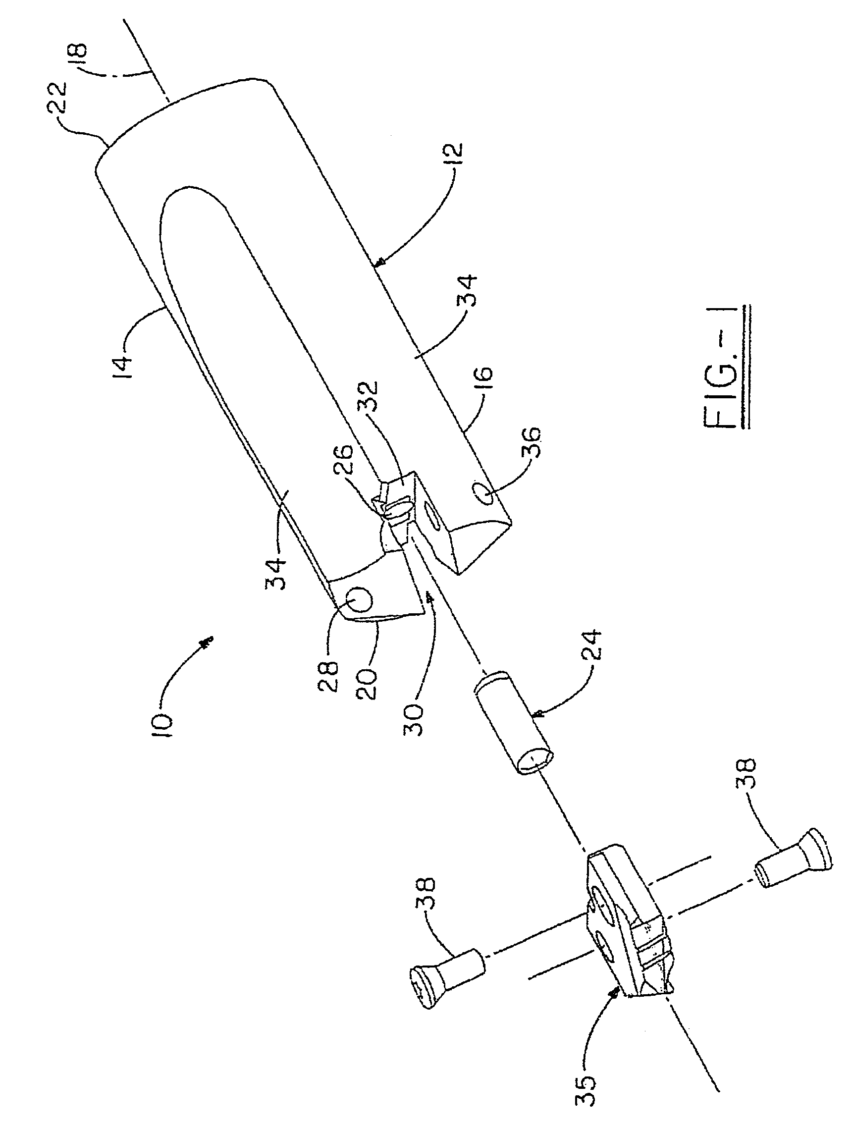
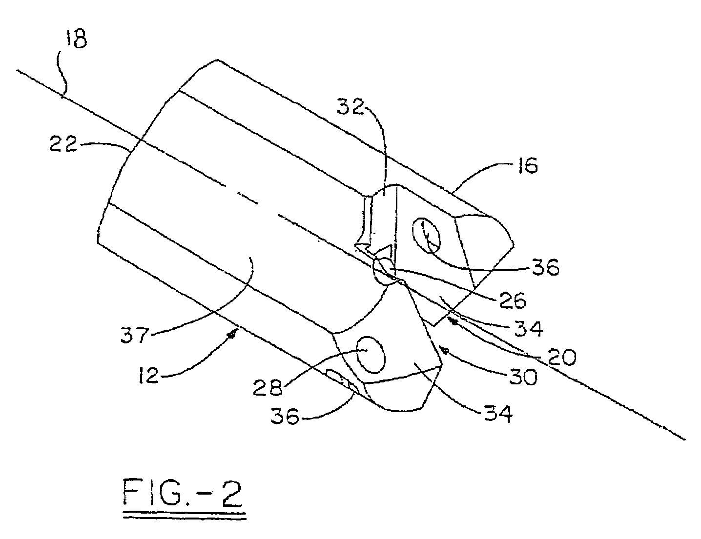
[0015]Turning now to a preferred embodiment of the invention, FIG. 1 illustrates a drill tool assembly 10 generally indicated. Drill tool assembly 10 comprises a holder 12, which has a body 14 and head portion 16 associated therewith. In the preferred embodiment, holder 12 has, in general, a cylindrical shape with a first end 20 and second end 22. As shown in FIG. 2, the first end 20 of holder 12 has a clamping or holder slot 30, which may extend across the entire diameter of the head portion 16 or, at least, over a center portion thereof at the general location of the rotational axis 18 of holder 12. The holder slot 30 has a bottom wall 32 positioned in substantially perpendicular orientation relative to the rotational axis 18 of the holder 12. In the preferred embodiment, the assembly 10 may further include a locating boss or dowel pin 24, which is positioned precisely with respect to the axis 18 and extends from the bottom wall 32 of the holder slot 30. The pin 24 may be position...


PUM

PropertyMeasurementUnit
rake angleaaaaaaaaaa
radiusaaaaaaaaaa
convex radiusaaaaaaaaaa

Abstract

The present invention relates to a V-notched web formed on a drill insert of a drill tool assembly. The V-notched web allows greater stability and feed rates, while decreasing the heat generated at the insert tip. The present invention is provided by a drill insert comprising a drill insert body having at least two cutting edges, a web between the two cutting edges, and a web thinning notch formed on either side of the web. Each web thinning notch forms a notch cutting edge having a positive rake angle.

Description

[0001]This application is a continuation-in-part of U.S. application Ser. No. 10 / 771,177 filed Feb. 2, 2004, now issued as U.S. Pat. No. 6,986,628, which is a continuation-in-part of U.S. application Ser. No. 09 / 975,221 filed Oct. 11, 2001, now issued as U.S. Pat. No. 6,685,402, which claims the benefit of U.S. Provisional Application No. 60 / 278,977, filed Mar. 27, 2001, all of which are hereby incorporated by reference.TECHNICAL FIELD[0002]The invention relates generally to a cutting insert to be placed into a tool holder for boring holes into metals. More specifically, the invention relates to a cutting tool insert having a specialized geometry at the web of the insert, allowing increased stability at various feed rates.BACKGROUND OF THE INVENTION[0003]Drilling systems are frequently used to provide cylindrical holes in metallic workpieces. The cutting or boring action of the drill system may be carried out by an elongated, substantially cylindrical drilling tool, such as a combin...

Claims


Application Information

Patent Timeline
Patent Type & Authority Patents(United States)
IPC IPC(8): B23B51/00
CPCB23B51/0009B23B2222/16Y10T408/9097B23B2226/125B23B2226/18B23B2226/31B23B2226/315B23B2251/02B23B2251/085B23B2251/14B23B2251/18B23B2251/48B23B2251/50B23B2270/08Y10S408/713Y10T408/909Y10T408/90993B23B2222/32B23B51/00035
Inventor MAST, WENDELL E.NUZZI, JOSEPH P.
Owner ALLIED MASCH & ENG CORP
Why Eureka
Try Eureka