Injection mold

a technology of injection molds and injection molds, which is applied in the field of injection molds, to achieve the effect of improving the durability of injection molds and increasing the peeling resistance of heat insulating coatings

Inactive Publication Date: 2006-10-03
CANON KK
View PDF6 Cites 5 Cited by
  • Summary
  • Abstract
  • Description
  • Claims
  • Application Information

AI Technical Summary

Benefits of technology

[0011]In the present invention having the above arrangements, even when the sliding member is repetitively linearly moved as it is guided by the adjacent member, a load such as the frictional force is not applied on the edge of the heat insulating coat with which at least one of the sliding member and adjacent member is coated. Since this increases the peeling resistance of the heat insulating coat, the durability of the injection mold improves.

Problems solved by technology

Unfortunately, the above prior art has the following unsolved problem.

Method used


Image

  • Injection mold
  • Injection mold
  • Injection mold

Examples


experimental example 1

[0057]An injection mold having an ejector pin as a sliding member was used in injection molding an injection molding product by changing the combination of the arrangement of the ejector pin and the arrangement of an adjacent member, and the number of times of injection molding before a heat insulating coat peeled was checked. The results are shown in FIGS. 14 and 15.

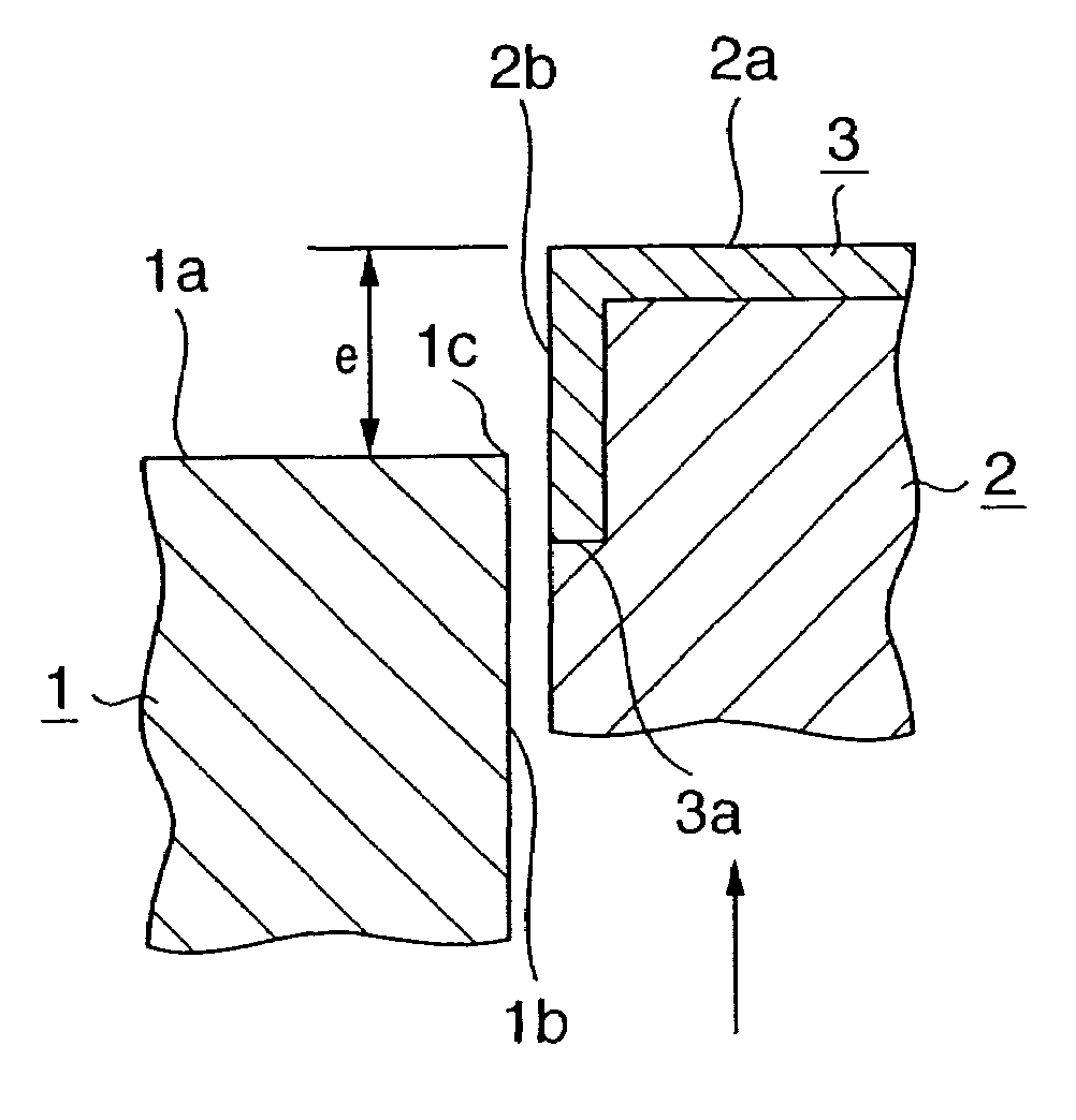
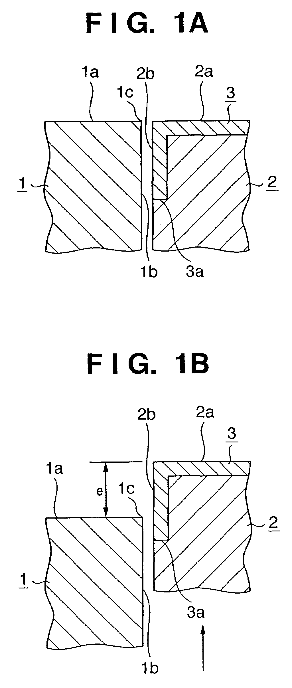
[0058]Note that as the arrangement of the sliding member and the arrangement of the adjacent member in Examples 1 to 35 shown in FIG. 14, the arrangements of the sliding members shown in FIGS. 1, 4, 5, 6, 7, and 10 were used.

[0059]Note also that in each of Examples 1 to 35, a 0.1 mm thick polyimide vacuum deposited polymerized coat (manufactured by VACUUM METALLURGICAL CO., LTD.) was used as the heat insulating coat, and a 0.001 mm thick CrN coat was used as the protective coat.

[0060]FIG. 12 is a schematic partial sectional view of an injection mold used in Comparative Example 1. The injection mold of this comparative e...

experimental example 2

[0066]The combination of the sliding member (FIG. 8) and the adjacent member (FIG. 1) in Example 11 described above was used to check the number of times of injection molding before the heat insulating coat peeled by changing the material of the protective coat. The results are shown in FIG. 16. Note that electroless plating, physical vapor deposition, and chemical vapor deposition were used as coat formation methods, and thickness of the protective coat was set to 1 μm. As shown in FIG. 16, in each of Examples 37 to 44, 10,000 times or more of injection molding were necessary before the heat insulating coat peeled, indicating high durability.

[0067]In each of the above embodiments as described above, the peeling resistance of the heat insulating coat is high, and this improves the durability. Therefore, high-quality injection molded products having excellent outer appearance can be stably molded.


PUM

PropertyMeasurementUnit
thickaaaaaaaaaa
thickaaaaaaaaaa
thicknessaaaaaaaaaa

Abstract

An injection mold includes a sliding member having a partial cavity surface which forms part of a cavity surface, and an adjacent member having a partial cavity surface which forms part of the cavity surface. A sliding surface of the sliding member is guided by a sliding surface of the adjacent member and is linearly movable by a relative sliding distance. A portion from the partial cavity surface to the sliding surface of at least one of the sliding member and adjacent member is continuously coated with a heat insulating coat, and a range over which the sliding surface is coated with the heat insulating coat is so set as to exceed an end of the relative sliding distance, where an edge of the partial cavity surface of the adjacent member contacts with the sliding surface of the sliding member.

Description

FIELD OF THE INVENTION[0001]The present invention relates to an injection mold in which at least a portion of the cavity surface is coated with a heat insulating coat, and which is used in plastic injection molding.BACKGROUND OF THE INVENTION[0002]As an injection mold having improved cavity surface transfer properties, an injection mold having a heat insulating structure (Japanese Patent Laid-Open No. 53-86754) is conventionally known. The surface transfer properties of this injection mold are improved by interposing a heat insulating material layer between a thin metal layer forming the cavity surface and a backing material, thereby decreasing the cooling rate of an injection-molded product during injection molding.[0003]Unfortunately, the above prior art has the following unsolved problem.[0004]An injection mold uses sliding members, such as an ejector pin, slide core, and inclined core, having partial cavity surfaces which form portions of the cavity surface. Each of these slidin...

Claims


Application Information

Patent Timeline
Patent Type & Authority Patents(United States)
IPC IPC(8): B29C45/83B29C45/26B29C33/56B29C45/37
CPCB29C33/56B29C45/37Y10S149/111
Inventor MIZUTA, YASUSHIARAI, TAKASHI
Owner CANON KK
Why Eureka
Try Eureka