Lapping system with mutually stabilized lapping carriers

a technology of lapping carrier and mutual stabilization, which is applied in the field of lapping apparatus, can solve the problems of crowning, increased friction between the lapping carrier b, and unsatisfactory condition known as crowning

Inactive Publication Date: 2006-10-03
IBM CORP
View PDF15 Cites 11 Cited by
  • Summary
  • Abstract
  • Description
  • Claims
  • Application Information

AI Technical Summary

Benefits of technology

[0010]Lapping forces can be applied independently to each lapping carrier and the lapping force on one lapping carrier will not increase the lapping force on the other lapping carrier. The interconnecting stabilizer arms will substantially prevent rotation of the lapping carriers that would otherwise cause unwanted rocking of the workpieces.

Problems solved by technology

By way of background, the conventional fixturing of a magnetic head wafer workpiece for lapping can lead to an undesirable condition known as crowning.
The problem with this standard technique for controlling crowning is that friction is increased between the lapping carrier 4 and the pads 14.

Method used


Image

  • Lapping system with mutually stabilized lapping carriers
  • Lapping system with mutually stabilized lapping carriers
  • Lapping system with mutually stabilized lapping carriers

Examples


Embodiment Construction

[0026]The invention will now be described by way of exemplary embodiments shown by the drawing figures, in which like reference numerals indicate like elements in all of the several views.

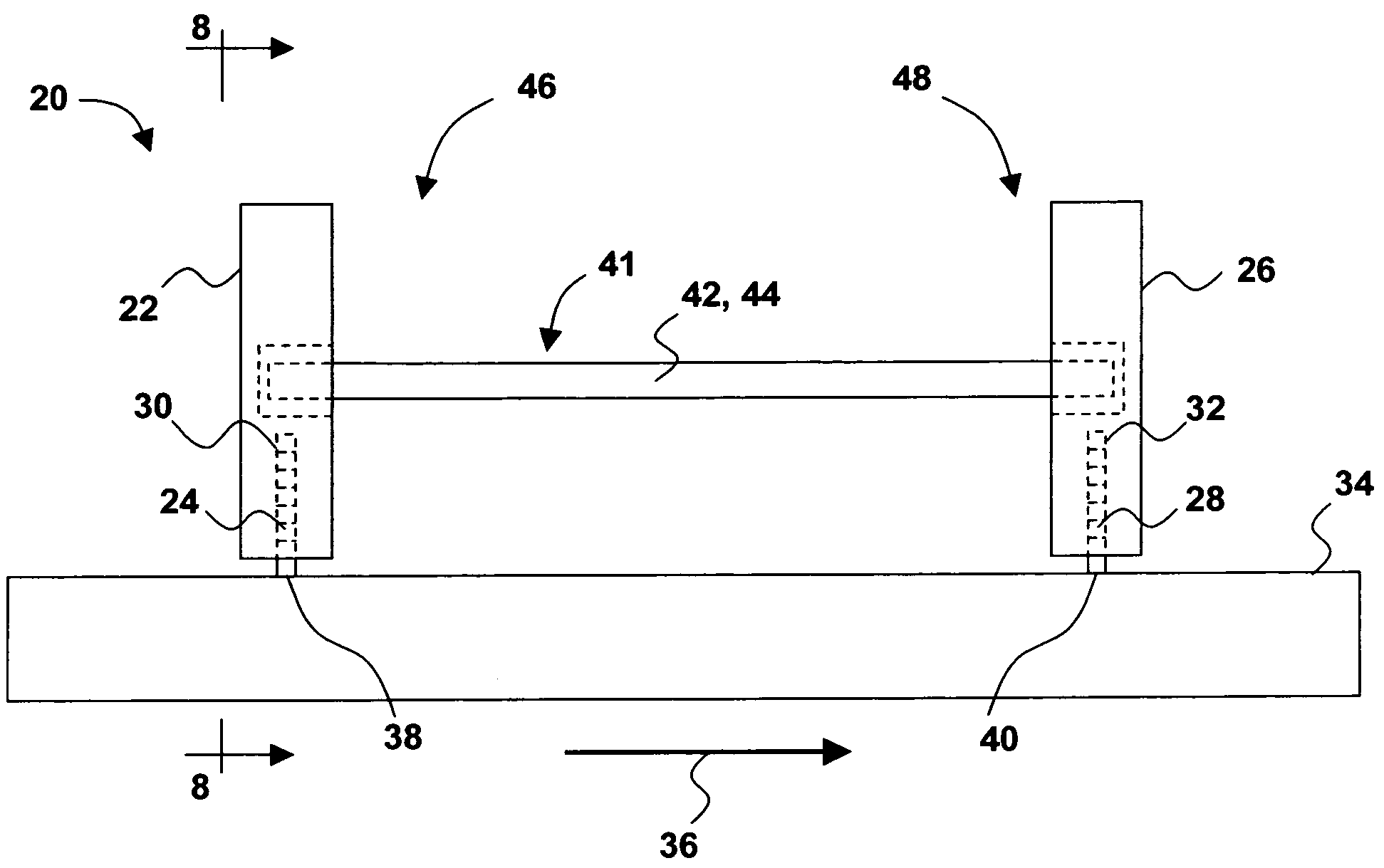
[0027]Turning to FIGS. 5–9 (not to scale), a lapping system 20 includes a first lapping carrier 22 adapted to carry a first workpiece 24 and a second lapping carrier 26 adapted to carry a second workpiece 28. Each workpiece 24 and 28 represents a magnetic head wafer element comprising a matrix of individual slider units arranged in a plurality of row bars. The workpieces 24 and 28 may contain any desirable number of horizontal rows and vertical columns of slider units. For example, each workpiece 24 and 28 may comprise a wafer quarter-section (sometimes referred to as a “quad”), a wafer eighth-section (sometimes referred to as a “miniquad”), or even a single row bar. Each row bar includes a single row of adjacent slider units. The slider units may be of the type conventionally used in magnetic disk...


PUM


Abstract

A lapping system for eliminating crowning in a surface to be lapped includes a first lapping carrier adapted to carry a first workpiece and a second lapping carrier adapted to carry a second workpiece. A stabilizer assembly interconnects the first and second lapping carriers in a mutually stabilizing arrangement that stabilizes the first and second workpieces against rotation. The stabilizer assembly includes first and second stabilizer arms extending between the first lapping carrier and the second lapping carrier. Each lapping carrier and an associated stabilizer arm collectively defines a fixture having a carrier portion and a stabilizer portion, and which may be generally T-shaped. One end of each stabilizer arm is cantilevered from its associated lapping carrier, while the free end of each stabilizer arm is pivotally mounted to the opposite lapping carrier. Downward lapping forces are applied independently to each lapping carrier. In an alternative embodiment, the stabilizer arm extending from the lapping carrier is mounted to an anchor that is not another lapping carrier.

Description

BACKGROUND OF THE INVENTION[0001]1. Field of the Invention[0002]This invention relates to the manufacture of magnetic heads used in magnetic storage devices such as disk drives and tape drives. More particularly, the invention is directed to an improved lapping apparatus that reduces or eliminates rocking motion during the lapping of magnetic head wafers comprising multi-slider row bars.[0003]2. Description of the Prior Art[0004]By way of background, the conventional fixturing of a magnetic head wafer workpiece for lapping can lead to an undesirable condition known as crowning. Crowning occurs when the row bar surface being lapped is allowed to rock during lapping, thus creating unwanted facets. FIGS. 1–4 (not to scale) are illustrative. These figures show a workpiece 2 secured in a lapping carrier 4 (sometimes referred to as a “magazine”) that is in turn slidably mounted in a reference fixture 6 (sometimes referred to as a “nest”). The workpiece 2 is assumed to comprise a matrix of...

Claims


Application Information

Patent Timeline
Patent Type & Authority Patents(United States)
IPC IPC(8): B24B41/06B24B7/00
CPCB24B37/30G11B5/102G11B5/3169G11B5/3173G11B5/1272G11B5/1871
Inventor BISKEBORN, ROBERT G.
Owner IBM CORP
Why Eureka
Try Eureka